


F-24
TROUBLESHOOTING AND REPAIR
F-24
LN-10
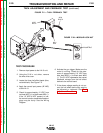
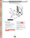
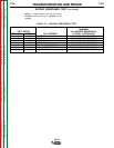
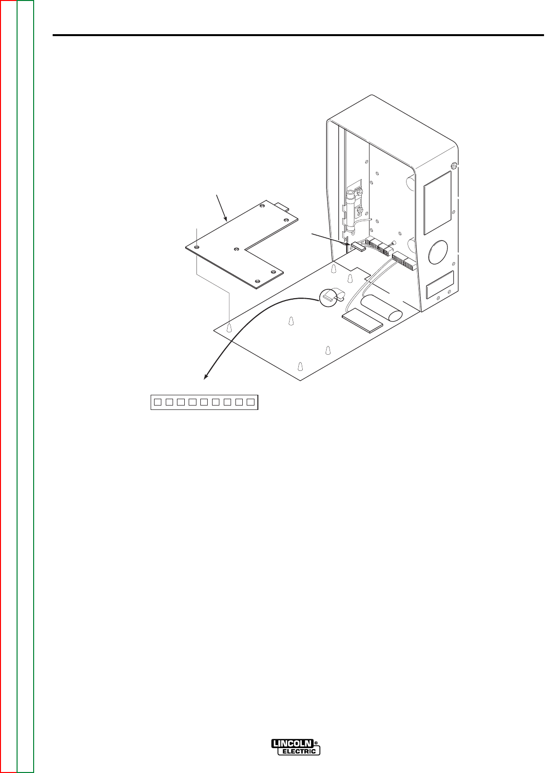
6. Check the keypad resistances referenc-
ing Figure F.3 and Table F.1.
7. The resistances are checked at plug
J10 on the keypad. See Figure F.3.
8. If any of the resistances are not correct,
the keypad may be faulty.
9. When test is complete, carefully install
the display board and connect plugs
J10 and J11.
10. Reassemble the front panel.
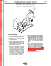
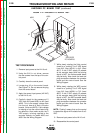
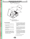
TEST PROCEDURE
1. Remove input power to the LN-10 unit.
2. Using the 5/16 in. nut driver, remove
the two screws from the top of the con-
trol panel. See Figure F.3.
3. Carefully lower the control panel.
4. Remove plug J11 from the display
board.
5. Perform the Display Board Removal
Procedure.
FIGURE F.3 — KEYPAD RESISTANCE TEST.
DISPLAY
BOARD
J11
J10
11
3355
77
99
22
44
66
8 8
KEYPAD RESISTANCE TEST (continued)
Return to Section TOC Return to Section TOC Return to Section TOC Return to Section TOC
Return to Master TOC Return to Master TOC Return to Master TOC Return to Master TOC