


A-9
INSTALLATION
LN-10
A-9
ELECTRICAL INSTALLATION
Input Cable: LN-10 Control to Power
Source
Available Cable Assemblies:
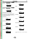
K1501 (Control Cable Only) Consists of a 9-conductor
control cable with a 14-pin control cable plug, without
electrode cable, and is available in lengths of 10 ft. (3
m), 17 ft. (5 m), 25 ft. (7.6 m), 33 ft. (10 m), 50 ft. (15
m) and 100 ft. (30 m).
K1502 Consists of a 9-conductor control cable with a
14-pin plug and a 3/0 (85 mm2 ) electrode cable with
stud terminal. It is rated at 600 amps, 60% duty cycle
and is available in lengths of 10 ft. (3 mm), 17 ft. (5
m), 25 ft. (7.6 m), 33 ft. (10 m) and 50 ft. (15 m) and
100 ft. (30 m) is also available with a 4/0 (107 mm2)
electrode cable.
K1503 Consists of a 9-conductor control cable with a
14-pin plug and 2/0 (67 mm2) electrode cable with
Twist-Mate™ connector. It is rated at 500 amps, 60%
duty cycle and is available in lengths of 10 ft. (3 m), 17
ft. (5 m), 25 ft. (7.6 m), 33 ft. (10 m) and 50 ft. (15 m)
and 100 ft. (30 m) is also available with a 3/0 (85
mm2)electrode cable.
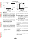
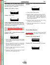
With input power disconnected from the power
source, install the input cable per the following:
1) Connect the end of the control cable with the 14-
pin cable plug to the mating receptacle on the
power source.
2) Connect the electrode lead to the power source
output terminal of the desired polarity.
3) Connect the 9-socket plug of the control cable to
the mating receptacle on the bottom of the LN-10
control box.
4) Slip the current sensor cover off enough to expose
the input connector stud. Connect the electrode
cable from the power source to this stud with the
nut provided, then reclose the current sensor
cover.
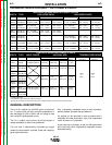
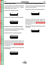
Work Cable
Connect a work lead of sufficient size and length (per
the following table) between the proper output termi-
nal on the power source and the work. Be sure the
connection to the work makes tight metal-to-metal
electrical contact.
Observe all additional Safety Guidelines detailed throughout this manual.
ELECTRIC SHOCK can kill.
• Do not touch electrically live parts such
as output terminals or internal wiring.
•
When inching with gun trigger, electrode and
drive mechanism are “hot” to work and
ground and could remain energized several
seconds after the gun trigger is released.
• Turn OFF input power at welding power
source before installation or changing
drive roll and/or guide tubes.
• Welding power source must be connected
to system ground per the National
Electrical Code or any applicable local
codes.
• Only qualified personnel should
perform this installation.
WARNING
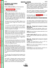
Copper Work Cable Size, AWG
Up to 100 ft Length (30m)
Current
60% Duty
Cycle
400 Amps
500 Amps
600 Amps
00 (67 mm
2
)
000 (85 mm
2
)
000 (85 mm
2
)
Return to Section TOC Return to Section TOC Return to Section TOC Return to Section TOC
Return to Master TOC Return to Master TOC Return to Master TOC Return to Master TOC