


F-36
TROUBLESHOOTING AND REPAIR
F-36
LN-10
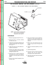
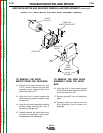
7. Remove harness plug J17 from the
encoder PC board.
8. Install harness plug J17 into the new
encoder PC board.
9. Assemble the PC board into the front
panel and secure with the washer and
nut previously removed.
10. Assemble the felt washer, spacer and
control knob onto the shaft and secure
with the 5/64 in. Allen wrench.
11. Replace the control panel.
PROCEDURE
1. Remove input power to the LN-10 unit.
2. Using the 5/16 in. nut driver remove the
two screws from the top of the control
panel.
3. Lower the control panel.
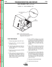
4. Using the 5/64 in. Allen wrench remove
the control knob, spacer and felt
washer from the encoder board that is
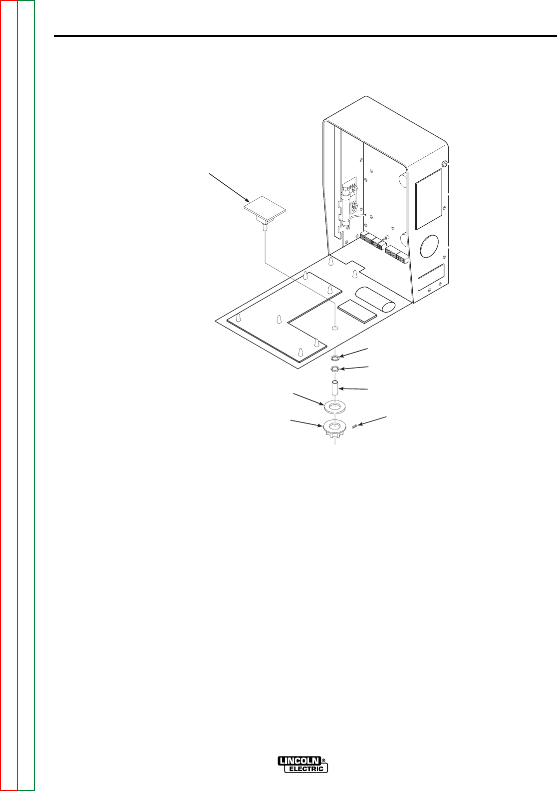
to be removed. See Figure F.8.
5. Using the 1/2 in. wrench remove the
nut and washer from the control shaft.
6. Carefully remove the PC board from
the front panel.
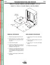
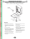
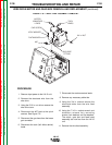
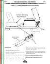
FIGURE F.8 — ENCODER PC BOARD REMOVAL AND REPLACEMENT.
ENCODER PC BOARD REMOVAL AND REPLACEMENT (continued)
ENCODER
PC BOARD
WASHER
NUT
SPACER
ALLEN
SCREW
FELT WASHER
KNOB
Return to Section TOC Return to Section TOC Return to Section TOC Return to Section TOC
Return to Master TOC Return to Master TOC Return to Master TOC Return to Master TOC