


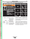
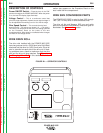
4. Using the instructions in Figure A.3, have a qual-
ified electrician connect the receptacle or cable to
the input power lines and the system ground per
the U.S. National Electrical Code and any applic-
able local codes. See Technical Specifications
at the beginning of this chapter for proper wire
sizes. For long runs over 100 feet, larger copper
wires should be used. Fuse the two hot lines with
super lag type fuses as shown in the following dia-
gram. The center contact in the receptacle is for
the grounding connection. A green wire in the
input cable connects this contact to the frame of
the welder. This ensures proper grounding of the
welder frame when the welder plug is inserted into
the receptacle.
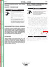
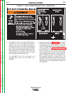
3. The 208/230 volt 60 Hz model POWER MIG is
shipped with a 10 ft. input cable and plug con-
nected to the welder. A matching receptacle is
supplied with the machine. Mount the receptacle
in a suitable location using the screws provided.
Be sure it can be reached by the plug on the input
cable attached to the welder. Mount with the
grounding terminal at the top to allow the power
cable to hang down without bending.
The 230/460/575 volt 60 Hz model is not
equipped with a plug, an input cable, or a
receptacle.
A-4
INSTALLATION
POWER MIG 255C
A-4
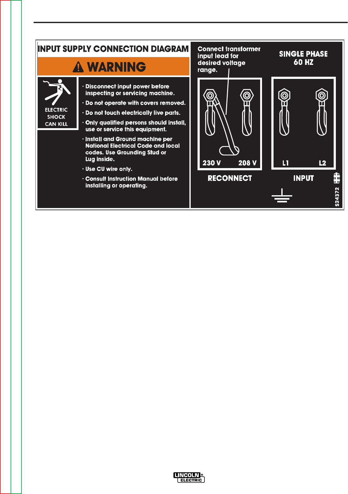
FIGURE A.1 — DUAL VOLTAGE MACHINE INPUT CONNECTIONS.
Return to Section TOC Return to Section TOC Return to Section TOC Return to Section TOC
Return to Master TOC Return to Master TOC Return to Master TOC Return to Master TOC