


E-5
THEORY OF OPERATION
POWER MIG 255C
E-5
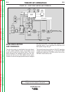
WIRE DRIVE MOTOR
AND FEEDBACK
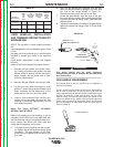
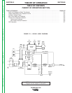
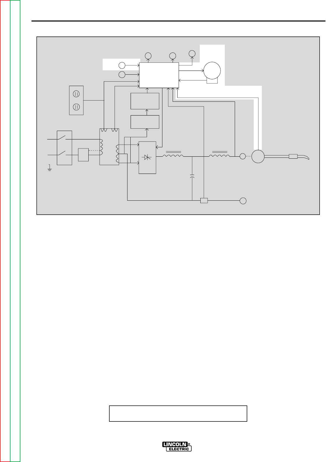
The wire drive motor is controlled by the control board.
A motor speed feedback signal is generated at the
motor tach and sent to the control board. The control
board compares this feedback signal with the com-
mands set forth by the Wire Speed Control poten-
tiometer and sends the appropriate armature voltage to
NOTE: Unshaded areas of Block Logic
Diagram are the subject of discussion
FIGURE E.5 — WIRE DRIVE MOTOR AND FEEDBACK.
LINE
SWITCH
RECONNECT
MAIN
TRANSFORMER
SNUBBER
BOARD
RECTIFIER
DIODE
BRIDGE
ARC
VOLTAGE
WIRE
SPEED
GAS
SOLENOID
FAN
MOTOR
CONTROL
BOARD
WIRE
DRIVE
MOTOR
TACH
GUN TRIGGER
FEEDBACK
115 VAC
30 VAC
G
A
T
E
S
I
G
N
A
L
SCR
RECTIFIER
POWER
ENHANCEMENT
CHOKE
OUTPUT
CHOKE
C
A
P
A
C
I
T
O
R
S
F
E
E
D
B
A
C
K
NEGATIVE
TERMINAL
POSITIVE
TERMINAL
SHUNT
SPOOL
GUN
AUX
the wire drive motor. The drive motor speed is thus
controlled which in turn regulates the electrode wire
feed speed through the gun.
The control board also provides a 3-24 VDC operating
voltage for the optional spool gun. To achieve full WFS
control at the spool gun, the WFS knob on front of the
PM-255C must be set at max.
Return to Section TOC Return to Section TOC Return to Section TOC Return to Section TOC
Return to Master TOC Return to Master TOC Return to Master TOC Return to Master TOC