


F-46
TROUBLESHOOTING AND REPAIR
F-46
POWER MIG 255C
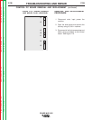
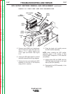
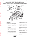
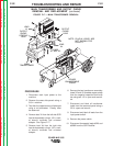
3. Disconnect lead #204 and heavy alu-
minum choke lead from the middle heat
sink with a 1/2 in. socket wrench and
1/2 in. open end wrench. See Figure
F.14.
4. Remove the diode lead from the nega-
tive capacitor band buss bar on the
right side of the machine using a 1/2 in.
socket and 3/8 in. open end wrench.
FIGURE F.14 — MIDDLE HEAT SINK
LEAD DISCONNECTION.
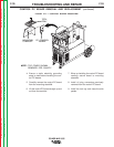
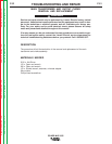
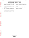
PROCEDURE
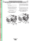
1. Remove the case side panels using a
3/8 in. nutdriver.
2. Disconnect lead #208S and trans-
former lead X1 from the heat sink on
the left side of the machine using a 1/2
in. socket wrench. See Figure F.13.
a. Thin lead is always on the outboard
side of the connection.
FIGURE F.13 — LEFT HEAT SINK
LEAD DISCONNECTION.
SCR OUTPUT RECTIFIER REMOVAL AND REPLACEMENT (continued)
LEAD X1
LEAD
#208S
LEFT
HEAT SINK
HEAVY
LEAD
LEAD
#204S
MIDDLE
HEAT SINK
Return to Section TOC Return to Section TOC Return to Section TOC Return to Section TOC
Return to Master TOC Return to Master TOC Return to Master TOC Return to Master TOC