


F-20
TROUBLESHOOTING AND REPAIR
F-20
POWER MIG 255C
4. Verify that the capacitors have
completely discharged with a volt-
ohmmeter.
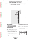
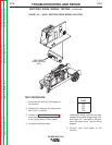
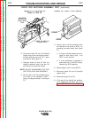
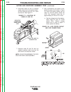
5. Disconnect plugs J6 and J5 from the
control board . This electrically isolates
the SCR bridge assembly. See Figure
F.3.
TEST PROCEDURE
1. Disconnect main AC input power to the
machine.
2. Remove the case top and side panels
with a 3/8 in. nutdriver.
3. Remove the tool tray with a 5/16 in. nut-
driver.
STATIC SCR RECTIFIER ASSEMBLY TEST (continued)
FIGURE F.3 — REMOVE PLUGS J6 AND J5 TO PERFORM STATIC RECTIFIER ASSEMBLY TEST.
J6
J5
J3
J8
J1
J4
J2
Return to Section TOC Return to Section TOC Return to Section TOC Return to Section TOC
Return to Master TOC Return to Master TOC Return to Master TOC Return to Master TOC