


OPERATION
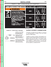
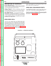
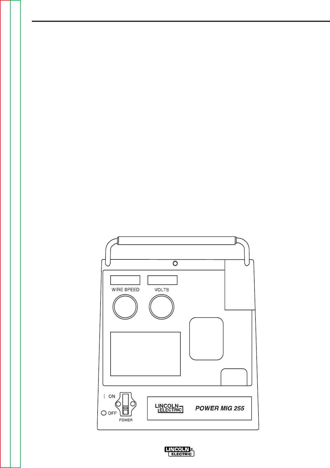
DESCRIPTION OF CONTROLS
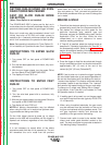
Power ON/OFF Switch — Place the lever in the "ON"
position to energize the POWER MIG 255C. When the power
is on, the red LED display lights illuminate.
Voltage Control — This is a continuous control that
gives full range adjustment of power source output voltage. It
can be adjusted while welding over its 10 to 28 volt range.
Wire Speed Control — This controls the wire feed
speed from 50 – 700 inches per minute (1.2 – 17.8 m/min).
The control can be preset on the dial to the setting specified
on the Procedure Decal on the inside of the wire
compartment door. Wire speed is not affected when changes
are made in the voltage control.
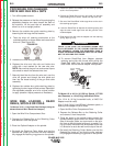
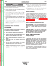
WIRE DRIVE ROLL
The drive rolls installed with the POWER MIG 255C
have two grooves one for .035(0.9mm) wire Solid Steel
electrode and the other for .045(1.2mm) wire. Drive roll
size is stenciled on each side of the drive roll. If feed-
ing problems occur, check to make sure that the wire
size and the drive roll size matches. See "Procedure
for Changing Drive Roll" in this section. This infor-
mation also appears on the Procedure Decal on the
door inside the wire compartment.
WIRE SIZE CONVERSION PARTS
The POWER MIG 255C is rated to feed .025 through
.045" (0.6-1.2 mm) solid or cored electrode sizes.
The drive roll kits and Magnum 250L gun and cable
parts are available to feed different sizes and types of
electrodes. See Accessories section.
POWER MIG 255C
B-4B-4
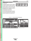
FIGURE B.1— OPERATOR CONTROLS
Return to Section TOC Return to Section TOC Return to Section TOC Return to Section TOC
Return to Master TOC Return to Master TOC Return to Master TOC Return to Master TOC