


F-14
TROUBLESHOOTING AND REPAIR
F-14
POWER MIG 255C
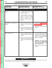
d. If ALL the voltages tested are incor-
rect or missing, go to step 16.
17. Test for correct nameplate input
voltage between the H1 lead at the
ON/OFF POWER SWITCH to H2 or
H3 (H5 if connected for 575 VAC) at
the reconnect panel. Voltage tested will
vary depending on input voltage
connection. See wiring diagram for test
point locations.
a. If the voltage test is incorrect,
-check for loose or broken leads
between the reconnect panel and
the ON/OFF POWER SWITCH.
-test the ON/OFF POWER
SWITCH for proper operation.
b. If the correct nameplate voltage is
being applied to the main trans-
former and one or more of the sec-
ondary voltages are missing or are
incorrect, the main transformer may
be faulty. Replace.
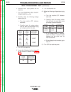
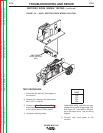
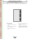
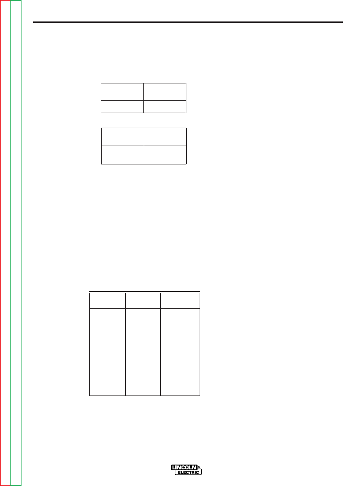
14. Locate the following leads on plug J5
on the Control PC board. See Figure
F.1.
15.
Turn the machine ON.
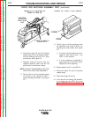
16. Make the following voltage tests at plug
J5 on the Control PC board.
a. Turn the machine OFF between
each test.
b. Carefully insert the meter probes
into the back of each Molex plug
pin cavity to perform the test.
c. If any of the voltages tested are
incorrect, check for loose or broken
leads between the test points and
the main transformer.
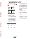
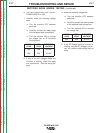
MAIN TRANSFORMER TEST (continued)
PLUG
LOCATION
3J5
LEAD
206
PLUG
LOCATION
2J5
1J5
LEAD
208
209
FROM
LEAD
208
(2J5)
208
(2J5)
209
(1J5)
TO
LEAD
209
(1J5)
206
206
EXPECTED
VOLTAGE
56VAC
28VAC
28VAC
Return to Section TOC Return to Section TOC Return to Section TOC Return to Section TOC
Return to Master TOC Return to Master TOC Return to Master TOC Return to Master TOC