


D-3
MAINTENANCE
D-3
POWER MIG 255C
Return to Section TOC Return to Section TOC Return to Section TOC Return to Section TOC
Return to Master TOC Return to Master TOC Return to Master TOC Return to Master TOC
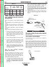
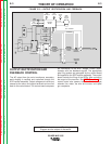
LINER REMOVAL, INSTALLATION
AND TRIMMING INSTRUCTIONS FOR
MAGNUM 250L
NOTE: The variation in cable lengths prevents
the
interchangeability of liners between guns. Once
a liner
has been cut for a particular gun, it should not be
installed in another gun unless it can meet the
liner
cutoff length requirement. Liners are shipped
with the
jacket of the liner extended the proper amount.
1. Remove the gas nozzle and nozzle insula-
tor, if used, to locate the set screw in the gas
diffuser which is used to hold the old liner in
place. Loosen the set screw with a 5/64"
(2.0 mm) Allen wrench.
2. Remove the gas diffuser from the gun tube.
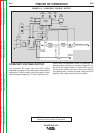
3. Lay the gun and cable out straight on a flat
surface. Loosen the set screw located in the
brass connector at the feeder end of the
cable and pull the liner out of the cable.
4. Insert a new untrimmed liner into the con-
nector end of the cable. Be sure the liner
bushing is stencilled appropriately for the
wire size being used.
Note: For liners KP1950-7, KP1950-8,
KP1955-1 and KP1599-2
Before fully seating the liner bushing, it will be
necessary to trim the liner’s inner tube flush with
the liner bushing using a sharp blade. After trim-
ming, remove any burrs from inner tube and
insure that the opening is fully open.
5. Fully seat the liner bushing into the connec-
tor. tighten the set screw on the brass cable
connector. The gas diffuser, at this time,
should not be installed onto the end of the
gun tube.
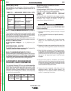
No. de Parte
No. de Parte del del Difusor de
Número de Tamaño Grabado Difusor de Gas Gas de la
Diámetro de Parte de la en el extremo del de la Tobera Fija Tobera ajustable
Electrodos Utilizados Guía Cilindro de la Guía (grabado) (grabado)
.025-.030" Steel KP1934-2 .030 (0.8 mm) KP2026-3 KP2026-2
(0.6-0.8 mm)
.035-.045" Steel KP1934-1 .045 (1.2 mm) KP2026-3 KP2026-1B1
(0.9-1.2 mm)
3/64" Aluminum KP1955-1 3/64" (1.2 mm) KP2026-3 KP2026-1B1
(1.2 mm)
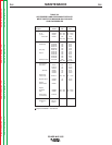
TABLE D.1
Diameter of
Electrode Used
Replace
ment
Line
Part
Number
Size
Stencilled on
End of liner
Bushing
Fixed Nozzle
Gas Diffuser
Part No. (and
stencil)
Adjustable
nozzle Gas
Diffuser
Part No.
(and
Stencil)
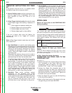
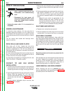
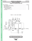
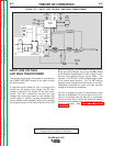
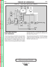
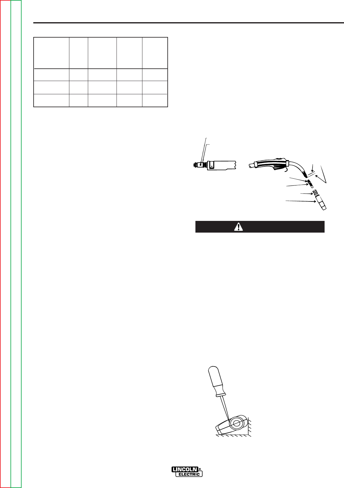
6. With the gas diffuser still removed from the gun
tube, be sure the cable is straight, and then trim
the liner to the length shown in Figure D.1.
Remove any burrs from the end of the liner.
7. Screw the gas diffuser onto the end of the gun
tube and securely tighten. Be sure the gas diffuser
is correct for the liner being used. (See table and
diffuser stencil.)
8. Tighten the set screw in the side of the gas diffuser
against the cable liner using a 5/64" (2.0 mm) Allen
wrench.
This screw should only be gently tightened.
Overtightening will split or collapse the liner and cause
poor wire feeding.
------------------------------------------------------------
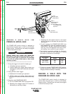
GUN HANDLE DISASSEMBLY
The internal parts of the gun handle may be inspected or
serviced if necessary.
The gun handle consists of two halves that are held together
with a collar on each end. To open up the handle, turn the
collars approximately 60 degrees counterclockwise (the same
direction as removing a right hand thread) until the collar
reaches a stop. Then pull the collar off the gun handle. If the
collars are difficult to turn, position the gun handle against a
corner, place a screwdriver against the tab on the collar and
give the screwdriver a sharp blow to turn the collar past an
internal locking rib.
TORNILLO DE FIJACION
TORNILLO DE FIJACION
CONECTOR DE CABLE DE COBRE
DIFUSOR DE GAS
AISLADOR DE TOBERA
(SI SE UTILIZA)
TOBERA DE GAS
1-1/4"
(31.8mm)
LONGITUD DE
CORTE
SET SCREW
BRASS CABLE CONNECTOR
SET SCREW
1-1/4 (31,8 mm)
LINER TRIM
LENGTH
GAS DIFFUSER
NOZZLE INSULATOR (IF USED)
GAS NOZZLE
FIGURE D.1
WARNING
counterclockwise