


F-31
TROUBLESHOOTING AND REPAIR
POWER MIG 255C
F-31
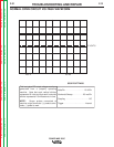
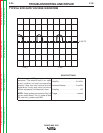
0 VOLTS
20.0 V 2.5 ms
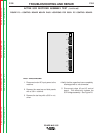
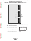
This is a typical DC output voltage waveform
generated from a properly operating
machine. Note that each vertical division
represents 20 volts and that each horizontal
division represents 2.5 milliseconds in time.
NOTE: Scope probes connected at
machine output terminals: (+) probe to elec-
trode, (-) probe to work.
Volts/Div . . . . . . . . . . . . . . . . . . 20 V/Div
Horizontal Sweep . . . . . . . . . 2.5 ms/Div
Coupling . . . . . . . . . . . . . . . . . . . . . . DC
Trigger . . . . . . . . . . . . . . . . . . . . Internal
SCOPE SETTINGS
NORMAL OPEN CIRCUIT VOLTAGE WAVEFORM
Return to Section TOC Return to Section TOC Return to Section TOC Return to Section TOC
Return to Master TOC Return to Master TOC Return to Master TOC Return to Master TOC