


THEORY OF OPERATION
E-2E-2
LN-23P
+
VOLTMETER
WIRE SPEED CONTROL
REDUCED SPEED CONTROL
GUN TRIGGER SWITCH
REED SWITCH ACTIVATED
GUN CONDUCTOR BLOCK
WIRE FEED MOTOR
BY WELDING CURRENT
VOLTAGE CONTROL
LN-23P
CONTROL
P.C. BOARD
3.5 A CIRCUIT
BREAKER
567
R12
R75
535
535
A
B
C
D
539
647
647
WORK
604
602
604
604
21
77
75
76
521
602
604
WORK (+)
ELECTRODE (-)
6 PIN CONNECTOR
8 PIN CONNECTOR
602
TP2
R76
1
1 23456
42536
541
641
BLACK
WHITE
642
67
521
567A
567
601
75
76
77
642
521
10KΩ, 4 W
82V, 12J
100Ω, 1 W
10KΩ, 4 W
A
B
C
G ECDH F
DCBAF E
644
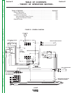
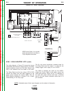
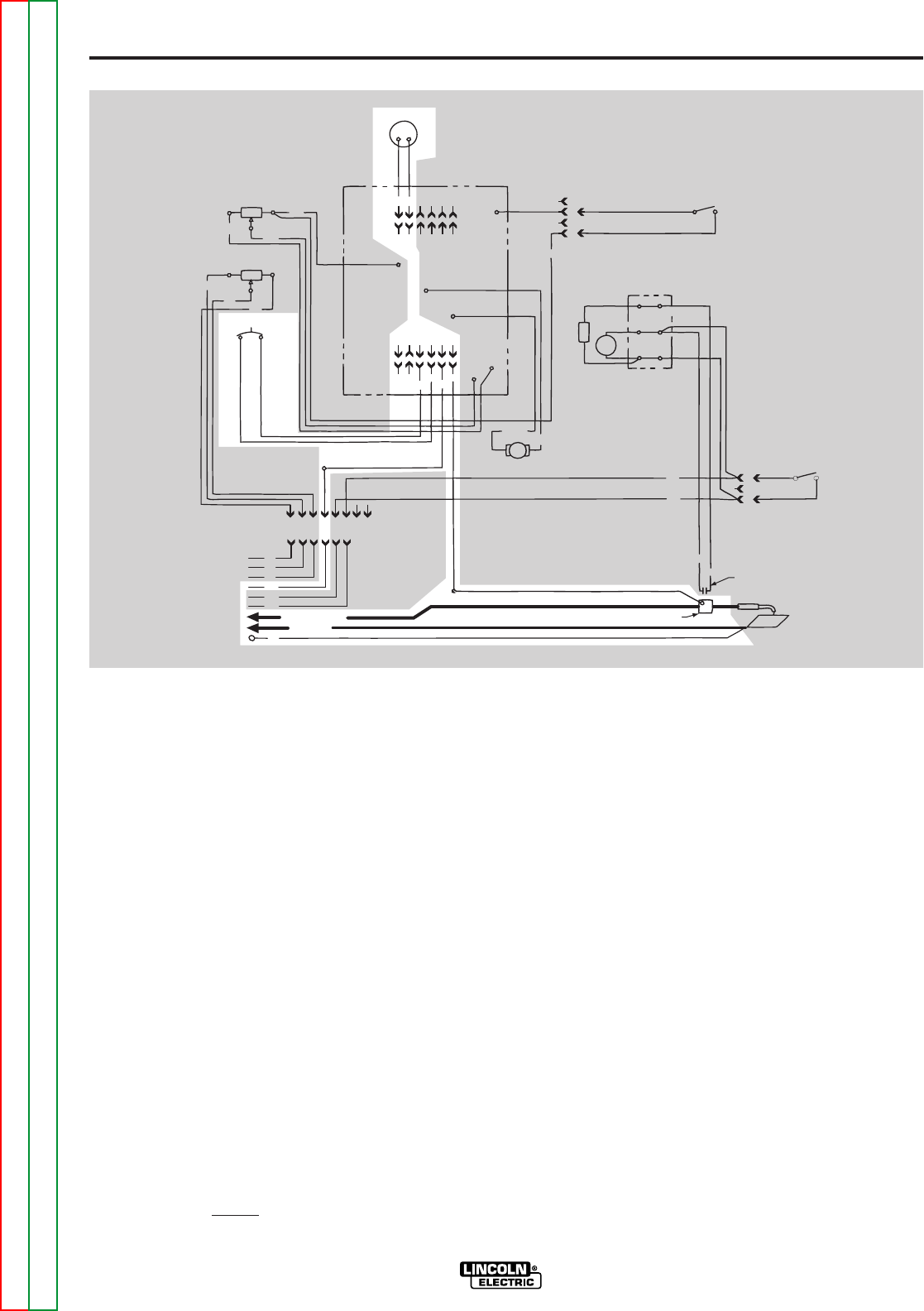
FIGURE E.2 – INPUT POWER CIRCUIT.
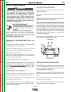
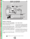
GENERAL DESCRIPTION
The LN-23P is an Arc Voltage powered, lightweight,
portable wire feed unit which includes calibrated wire
speed control, voltage control, and wire drive with an
enclosed 14 lb. wire reel, analog voltmeter and various
input control and electrode cables.
The LN-23P was designed specifically for Innershield
pipe welding, but, with the proper electrode, can be uti-
lized for general purpose welding. The machine is
internallly connected for negative polarity (DC-). It will
feed .068 or 5/64 Innershield wire using one of several
different gun cable assemblies. It is designed to be
used with any Lincoln constant voltage (CV) power
source that is suited to the operating range of those
wires.
Other features include a Wire Speed Reduction Switch
and a trigger interlock circuit which will be discussed in
more detail.
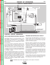
INPUT POWER CIRCUIT
The DC arc voltage from the power source is applied
to the LN-23P by way of the electrode cable (-)and the
Work Sensing Lead (+). . Typically the work connection
is through the control cable of the K350 Adapter. If no
adapter is used the connection is through the power
source. The voltage is then coupled to the Control
Board at lead 67 and 521.
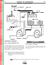
The electrode circuit (lead #67) is routed out of the
board (lead #567) to the 3.5 amp circuit breaker and
back to the board (lead 567A). The Circuit Breaker
provides protection for the board from motor overload.
Leads 567 and 521 are routed through the Control
Board to the Voltmeter. See Figure E.2.
NOTE: Unshaded areas of block logic diagrams are the subject of discussion.
Return to Section TOC Return to Section TOC Return to Section TOC Return to Section TOC
Return to Master TOC Return to Master TOC Return to Master TOC Return to Master TOC