


LN-23P
F-17 F-17
TROUBLESHOOTING AND REPAIR
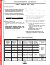
K350(-1) ADAPTER TEST (cont.)
TEST PROCEDURE
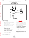
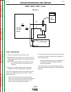
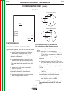
1. Connect a switched and grounded 120VAC supply
to terminals 31 & 32 of the Control Terminal Strip
and the ground stud (GND) as shown in Fig. F.5.
2. Connect two toggle or push button switches to ter-
minals 602 & 604 of the Wire Feed Tereminal strips.
3. Close the Power Switch (S1).
4. Check for 24VAC at terminals 605 &606 on the PC
Board.
If no voltage or incorrect voltage, check the
Control Transformer.
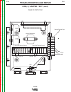
5. With an Ohmmeter or continuity tester, check for the
values listed in the troubleshooting chart (Fig.F.7),
under all three conditions, (Switch A&B open,
Switch A closed and Switch B closed).
6. When Switch A is closed, 1CR relay should function.
When Switch B is closed, 2CR relay should func-
tion.
a. If neither relay functions the PC Board may
be defective.
b. If one of the relays does not work, check for
24vdc at the relay coil. (See Wiring
Diagram).
If voltage is present, replace the relay.
If no voltage, check the wiring.
7. If all of the above tests are correct, check the
Control Cable for continuity on all leads. (See the
Wiring Diagram)
MEASUREMENT POINTS EXPECTED READING
CONTROL
TERMINAL
STRIP
WIRE FEED
TERMINAL
STRIP
SWITCH
A & B
OPEN
SWITCH A
CLOSED
B OPEN
SWITCH B
CLOSED
A OPEN
INCORRECT
READING
INDICATES
CORRECTIVE
ACTION
21 521A OPEN (∞)
SHORT (0Ω)
OPEN (∞) 1CR or PC Bd
Perform
tests in
Step 6
521B OPEN (∞) OPEN (∞)
SHORT (0Ω)
2CR or PC Bd
75 75A OPEN (∞)
SHORT (0Ω)
OPEN (∞) 1CR or PC Bd.
75B
SHORT (0Ω)
OPEN (∞)
SHORT (0Ω)
2CR or PC Bd.
76 76A OPEN (∞)
SHORT (0Ω)
OPEN (∞) 1CR or PC Bd.
76B
SHORT (0Ω)
OPEN (∞)
SHORT (0Ω)
2CR or PC Bd.
77 77A
SHORT (0Ω) SHORT (0Ω) SHORT (0Ω)
Wiring
Check for loose
or broken con-
nections
77B
SHORT (0Ω) SHORT (0Ω) SHORT (0Ω)
Wiring
4 to 2A ---- OPEN (∞)
SHORT (0Ω)
OPEN (∞) 1CR or PC Bd.
Perform
tests in
Step 6
4 to 2B ---- OPEN (∞) OPEN (∞)
SHORT (0Ω)
2CR or PC Bd.
FIGURE F.7 TROUBLESHOOTING CHART
WARNING
ELECTRIC SHOCK can kill.
• Only qualified personnel should perform this
installation, maintenance and troubleshooting
work.
• Turn off the input power at the fuse box before
working on other equipment connected to the
welding system at the disconnect switch or fuse
box before working on this equipment.
• Do not touch electrically hot parts.
Return to Section TOC Return to Section TOC Return to Section TOC Return to Section TOC
Return to Master TOC Return to Master TOC Return to Master TOC Return to Master TOC