


LN-23P
Return to Section TOC Return to Section TOC Return to Section TOC Return to Section TOC
Return to Master TOC Return to Master TOC Return to Master TOC Return to Master TOC
F-8 F-8
TROUBLESHOOTING AND REPAIR
WIRE FEEDER TEST (cont.)
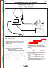
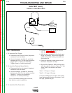
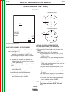
FIGURE F.1 FEEDER TEST SET-UP
TEST PROCEDURE
1. Remove the welding wire from the drive rolls.
Be careful not to release the loose end to
prevent tangling.
2. Connect leads 521 and 604 together.
3. Connect the DC Power Supply as shown:
Positive to Lead 602
Negtive to the Electrode Conductor Block.
4. Turn on the Power Supply and close the Gun
Trigger. The motor should run and the Wire
Feed Speed control should vary the speed
smoothly from MIN (30 ipm) to MAX (170 ipm).
5. Move Reduced Speed Switch to Position 2 and
see that motor speed decreases.
6. If the motor does not run or runs badly:
A. Check the trigger circuit. (See Gun Test).
B Perform the Feed Head Test.
C. Check the wire speed control. (See the
Potentiometer Test.
7. If the gun, the motor and the wire speed
control check OK, the Control Board may be
defective.
8. Perform the Calibration Check.
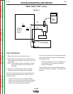
9. With an ohmmeter, check the control leads:
75 to 77 = 10kΩ
75 to 76 = 0 to 10kΩ as Volts control is
varied.
77 to 76 = 0 to 10kΩ as volts control is
varied.
If readings are not correct, check the cable
and/or perform the Potentiometer test.
75
76
77
602
604
521
25vdc Supply
Neg. Pos.