


LN-23P
Return to Section TOC Return to Section TOC Return to Section TOC Return to Section TOC
Return to Master TOC Return to Master TOC Return to Master TOC Return to Master TOC
F-10 F-10
TROUBLESHOOTING AND REPAIR
GUN TEST (cont.)
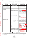
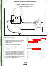
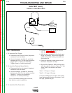
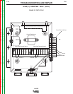
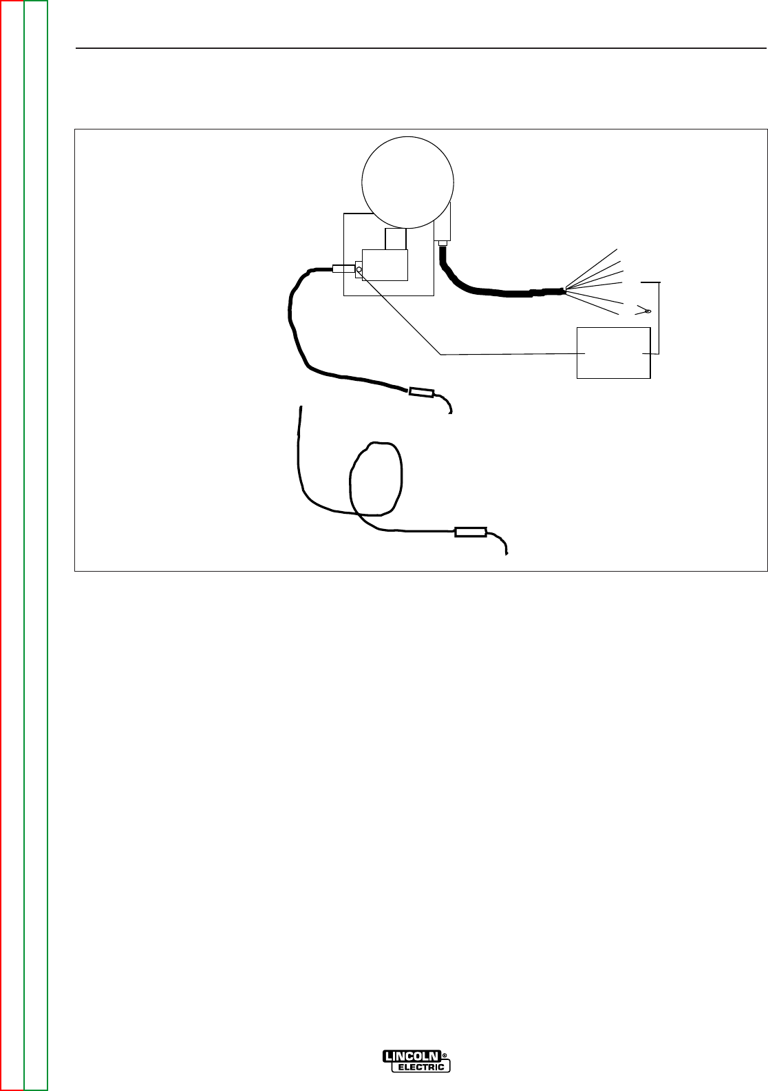
FIGURE F.2 GUN CABLE TESTS
TEST PROCEDURE
1. To check the Gun Trigger:
a. Disconnect the three pin (lower) Amphenol
connector from the feeder.
b. Use an ohmmeter to check for continuity
between pins A & C of the cable connector.
Trigger open = Infinity (no continuity).
Trigger closed = 0 ohms (continuity).
2. To check the Reduced Speed Switch:
a. Disconnect the four pin (upper) Amphenol
connector from the feeder.
b. Use an ohmmeter to check for continuity
between pins B & D of the cable connector.
Position 1 = Infinity (no continuity).
Position 2 = 0 ohms (continuity).
If any of the above readings are incorrect,
that switch or cable is defective.
3. To check the Wire Feed cable:
a, Connect a DC Power Supply to the LN-
23P. See Wire Feeder Test.
b. With the gun connected to the feeder and
laying out straight, feed wire through the
cable until several inches protrudes from
the contact tip.
c. Clamp an ammeter probe around one of
the motor wires (541 or 539).
d. Set the Wire Speed at MAX and feed wire
with the cable as shown in Figure F.2, Test
A and Test B and monitor the motor
current.
Test A - 1/2 loop >1.0 amps.
Test B - 14” loop >2.3 amps.
If current readings are too high, clean cable
(see Maintenance Section) and retest. If still
too high, replace the gun.
75
76
77
602
604
521
25vdc Supply
Neg. Pos.
14 Dia.
loop
1/2 loop
Return to Section TOC Return to Section TOC Return to Section TOC Return to Section TOC