


LN-23P
Return to Section TOC Return to Section TOC Return to Section TOC Return to Section TOC
Return to Master TOC Return to Master TOC Return to Master TOC Return to Master TOC
F-14 F-14
TROUBLESHOOTING AND REPAIR
POTENTIOMETER TEST (cont.)
TEST PROCEDURE
WIRE SPEED CONTROL POTENTIOMETER
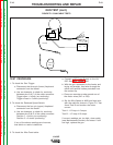
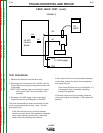
1. Disconnect leads 641, 642 and 535 from the Control
Board. (See Figure F.4)
a. Check resistance between lead 535 and
lead 641 for a reading of 10kΩ +/-10%.
A low reading or an ʻopenʼ reading indicates a
defective potentiometer.
b. Connect the ohmmeter to leads 641 and
642, and rotate the control slowly from min
to max speed setting.
The meter should vary smoothly from 10kΩ
to 0 Ω.
c. Repeat test ʻbʼ with meter connected to
leads 642 and 535.
Any irregularity or ʻskippingʼ in the meter read-
ing indicates a defective potentiometer.
d. Check all three leads to the potentiometer
case. Reading must be >500kΩ.
VOLTAGE CONTROL POTENTIOMETER
For codes above 10892 (8 pin connector)
1. Disconnect the Control Cable from the back of the
feeder.
NOTE: See Figure F.4 for Pin locations
a. Check resistance from Pin F(75) to Pin H
(77) of the box connector for a reading of
10kΩ +/- 10%.
A low reading or an ʻopenʼ reading indicates a
defective.
b. Connect the meter from Pin F(75) to Pin
G(76) and rotate the control slowly from min
to max voltage setting.
The meter should vary smoothly from 0 Ω to
10kΩs.
c. Repeat test ʻbʼ with meter connected to Pins
G and H.
Any irregularity or ʻskippingʼ in the meter read-
ing indicates a defective potentiometer.
d. Check all three leads to the potentiometer
case. Reading must be >500kΩ.
NOTE: Codes below 10892 have a 6 pin connector.
Test points will be pins E(75), D(76) and
F(77)
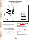
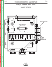
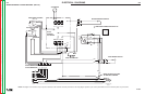
FIGURE F.4
LN-23P
Control
Board
535
641
642
F
A
B
C
D
E
G
A
B
C
D
E
F
H
Codes Below 10892
Codes 10892 & Above
76
75
77
77
75
76