


THEORY OF OPERATION
E-3E-3
LN-23P
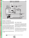
CONTROL CIRCUIT OPERATION
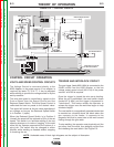
VOLTS AND SPEED CONTROL CIRCUITS
The Voltage Control is connected directly to the
K350 Adapter or the power source (if no adapter is
required) by leads 75, 76 & 77. It can be adjusted
while welding to provide the voltage called for by the
weld procedure.
The wire feed speed is controlled by signals to the
Control Board from the Speed Control and the
Reduced Speed Switch. The Wire Speed Control is
calibrated and can be preset to the desired value.
The speed will remain at the set value regardless of
arc voltage as long as the Reduced Speed Switch
is in Position 1 (open).
When the Reduced Speed Switch is in Position 2
(closed) the speed will be reduced to 83% of the set
speed. This switch is to facilitate welding if the root
opening changes or to reduce “sagging” of the weld
metal as the operator approaches the bottom of a
pipe joint. The switch may be changed to either
position while welding as needed without stopping
or breaking the arc.
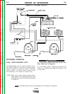
TRIGGER AND INTERLOCK CIRCUIT
The gun trigger (leads 602 & 604) is connected to the
24VAC circuit from the K350 Adapter, or the low
voltage output control circuit (#2 & #4) of the power
source if no K350 is required.
Once the trigger is closed the wire starts feeding.
When the arc is estblished, the reed switch closes
(leads 647 & 604) and the trigger is bypassed or
“interlocked”. This feature allows the operator to
release the trigger once the weld has begun to help
eliminate fatigue.
The reed switch is a magnetically operated device that
is mounted on a bracket above the block where the
gun connects to the feeder. It responds to the
magnetic field that is presnt due to the weld current
flowing through the gun cable.
To stop welding, the operator must physically pull the
gun away from the weld, thus stopping current flow
and releasing the reed switch. See Figure E.3.
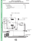
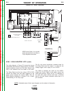
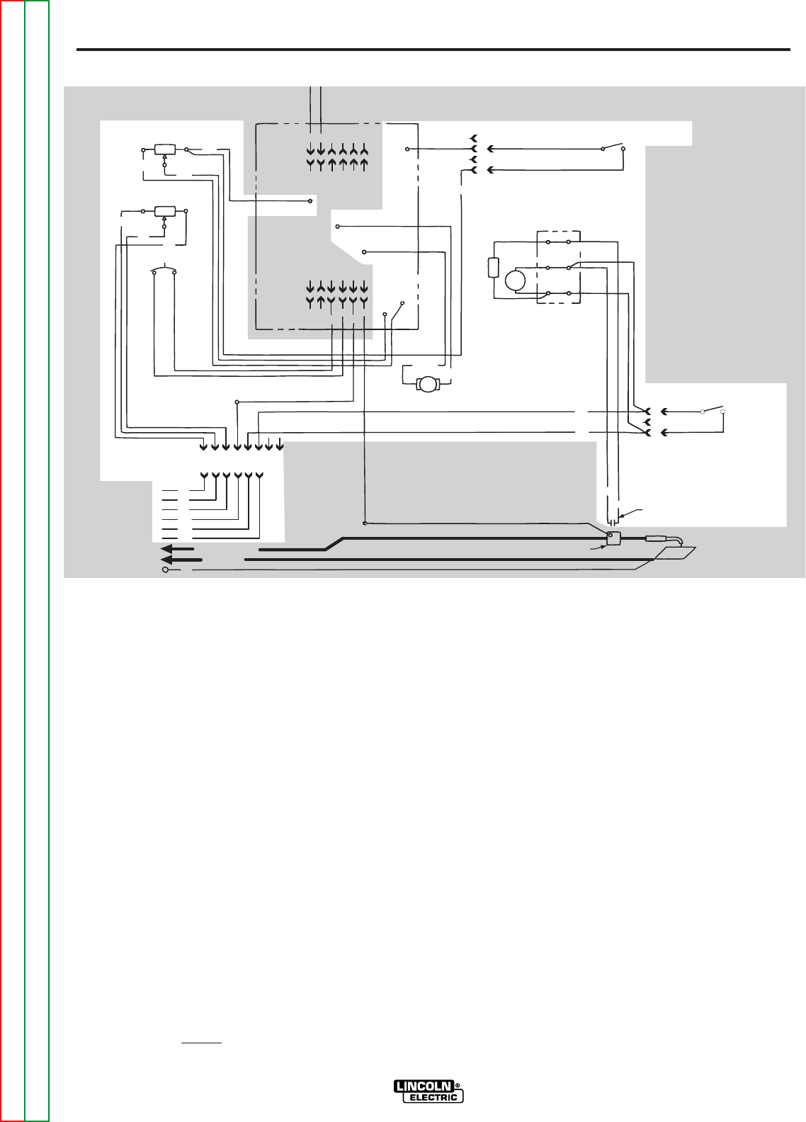
FIGURE E.3 – CONTROL CIRCUITS.
+
VOLTMETER
WIRE SPEED CONTROL
REDUCED SPEED CONTROL
GUN TRIGGER SWITCH
REED SWITCH ACTIVATED
GUN CONDUCTOR BLOCK
WIRE FEED MOTOR
BY WELDING CURRENT
VOLTAGE CONTROL
LN-23P
CONTROL
P.C. BOARD
3.5 A CIRCUIT
BREAKER
567
R12
R75
535
535
A
B
C
D
539
647
647
WORK
604
602
604
604
21
77
75
76
521
602
604
WORK (+)
ELECTRODE (-)
6 PIN CONNECTOR
8 PIN CONNECTOR
602
TP2
R76
1
123456
42536
541
641
BLACK
WHITE
642
67
521
567A
567
601
75
76
77
642
521
10KΩ, 4 W
82V, 12J
100Ω, 1 W
10KΩ, 4 W
A
B
C
GECDHF
DCBAF E
644
NOTE: Unshaded areas of block logic diagrams are the subject of discussion.
Return to Section TOC Return to Section TOC Return to Section TOC Return to Section TOC
Return to Master TOC Return to Master TOC Return to Master TOC Return to Master TOC