


Return to Section TOC Return to Section TOC Return to Section TOC Return to Section TOC
Return to Master TOC Return to Master TOC Return to Master TOC Return to Master TOC
F-2 F-2
TROUBLESHOOTING AND REPAIR
If for any reason you do not understand the test procedures or are unable to perform the
tests/repairs safely, contact the Lincoln Electric Service Department for technical
troubleshooting assistance before you proceed. Call 1-888-935-3877.
Service and Repair should only be performed by Lincoln Electric Factory Trained
Personnel. Unauthorized repairs performed on this equipment may result in danger
to the technician and machine operator and will invalidate your factory warranty. For
your safety and to avoid Electrical Shock, please observe all safety notes and
precautions detailed throughout this manual.
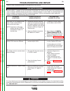
This Troubleshooting Guide is provided to help
you locate and repair possible machine
malfunctions. Simply follow the three step
procedure below.
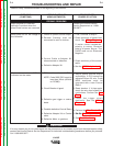
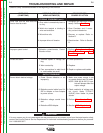
Step 1. LOCATE PROBLEM (SYMPTOM).
Look under the column labeled "PROBLEM"
(SYMPTOMS). This column describes possible
symptoms that the machine may exhibit. Find
the listing that best describes the symptom that
the machine is exhibiting. Symptoms are
grouped into three main categories: Output
Problems, Function Problems and LED Function
problems.
Step 2. PERFORM EXTERNAL TESTS. The
second column, labeled "POSSIBLE AREAS OF
MISADJUSTMENT(S)", lists the obvious
external possibilities that may contribute to the
machine symptom. Perform these tests/checks
in the order listed. In general, these tests can be
con-ducted without removing the case wrap-
around cover.
Step 3. PERFORM COMPONENT TESTS. The
last column, labeled "Recommended Course of
Action" lists the most likely components that may
have failed in your machine. It also specifies the
appropriate test procedure to verify that the sub-
ject component is either good or bad. If there are
a number of possible components, check the
components in the order listed to eliminate one
possibility at a time until you locate the cause of
your problem.
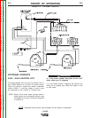
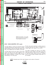
All of the referenced test procedures referred to
in the Troubleshooting Guide are described in
detail at the end of this chapter. Refer to the
Troubleshooting and Repair Table of Contents to
locate each specific Test Procedure. All of the
referred to test points, components, terminal
strips, etc., can be found on the referenced elec-
trical wiring diagrams and schematics. Refer to
the Electrical Diagrams Section Table of
Contents to locate the appropriate diagram.
WARNING
CAUTION
How To Use Troubleshooting Guide
IMPORTANT TROUBLESHOOTING TIPS:
The most common problem in multiple machine
installations is proper routing of the Weld cables,
control cables and remote sense leads. See the
information in Section A of this manual or in the
Operatorʼs Manual (IM848).
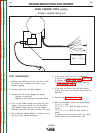
When trying to troubleshoot an AC/DC 1000 that
is in a multi arc, tandem and/or parallel weld cell
set up,it would be an advantage to use a known
good welder, wire feed head, or PF10A controller
to help isolate the problem with the system. If
replacing a component eliminates the problem,
the weld cell can be re-started and the defective
unit can possibly be repaired outside of the
working weld cell. This can help to minimize
down time.
Note: It is good practice to record the dip switch
arrangement before any changes are made. If
the machine is to be returned to the same
location, the proper re-setting the switches will
help facilitate the installation. When working on
welders that have been in a multi-arc or parallel
set-up, the dip switches on the control board &
ethernet board will have to be re-configured to
the factory “default” settings for Single arc
applications. The dip switch information can be
found in Section A of this manual or in the
Operatorʼs Manual (IM-848)under the heading
“Internal Controls”.
Once the welder is set for a single arc
application, troubleshooting can be done with a
single PF10A controller and , PF10S feed head
or with the diagnostic software that is packaged
with the Power Wave AC/DC 1000.