


Return to Section TOC Return to Section TOC Return to Section TOC Return to Section TOC
Return to Master TOC Return to Master TOC Return to Master TOC Return to Master TOC
LN-23P
If for any reason you do not understand the test procedures or are unable to perform the tests/repairs safely,
contact the Lincoln Electric Service Department for technical troubleshooting assistance before you proceed.
Call 1-888-935-3877.
CAUTION
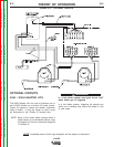
Since the K350 (-1) adapter is the communication link between the feeder and the power source,symptoms that
seem to indicate a defective feeder may be due to a defective adapter or control cable. If a working feeder and
cable is available, connecting it will help to isolate the problem. If this is not convenient, either replace the
adapter or follow the troubleshooting steps for the K350.
F-6 F-6
TROUBLESHOOTING AND REPAIR
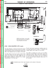
K350 ADAPTER PROBLEMS
Observe Safety Guidelines detailed in the beginning of this manual.
PROBLEMS
(SYMPTOMS)
POSSIBLE AREAS OF
MISADJUSTMENT(S)
RECOMMENDED
COURSE OF ACTION
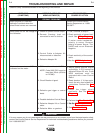
Motor wonʼt run. No voltage on the
meter. Feeder checks OK and
power source has output.
NOTE: Symptoms on this page
assume that the LN-23P is
connected to Feeder “A”
terminal strip
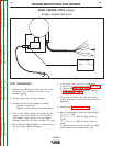
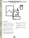
1. Disconnect the Work Sensing
lead from the terminal strip and
with power applied to the K350,
check for continuity from the #21
terminal to #521 on Feeder ”A”
Terminal strip.
2. Check for 24VAC at terminals
605 &606 at PC Board.
1. If reading is 0 ohms, check the
control cable to the LN-23P.
2. If the voltage is 0, check for
120vac at terminals #31 & #32.
3. Make sure the power source is
supplying 120vac to the cable.
4. Perform the K350 Adapter test.
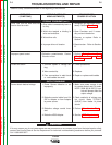
Motor wonʼt run when trigger is
pulled. OCV shows on voltmeter.
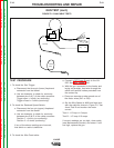
1. Temporarily jumper #602 from
terminal strip to #610.
1. If motor runs, check connections
to relay. Replace 2CR relay.
If motor does not run check
leads 602 & 604 from terminal
strip to PC Board and to 2CR.
No voltage control or cannot obtain
desired voltage.
1. Run test with the power source
in ʻLOCALʼ control.
2. Check the Voltage Control
potentiometer.
1. If desired voltage can be
achieved;
• Check cable from power
source to adapter.
• Check connections from
Feeder “A” terminal strip to
1CR.
2. Perform the Potentiometer
test.
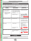
Feeder A works OK, Feeder B does
not
1. Make sure 2CR relay operates
when Feeder “B” trigger is
pulled.
1. If relay does not operate:
• Check wiring from Feeder”B”
terminal strip.
• Perform the K350 Adapter
test.