


OM-4405 Page 9
SECTION 2 – DEFINITIONS
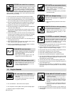
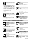
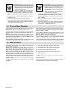
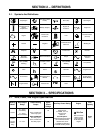
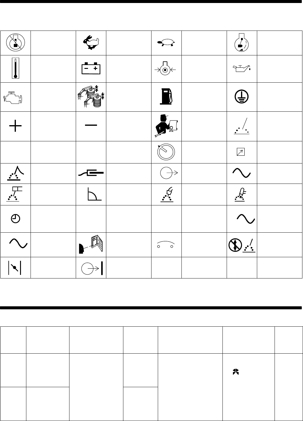
2-1. Symbols And Definitions
Stop Engine
Fast (Run, Weld/
Power)
Slow (Idle) Start Engine
Air Temperature Or
Engine
Temperature
Battery (Engine)
Engine Oil
Pressure
Engine Oil
Engine
Check Valve
Clearance
Fuel
Protective Earth
(Ground)
Positive Negative
Certified/Trained
Mechanic
Welding Arc
A
Amperes
V
Volts Panel/Local Remote
Electrode
Connection
Work Connection Output
Alternating
Current
Stick (SMAW)
Welding
Constant Current
(CC)
MIG (GMAW)
Welding
TIG (GTAW)
Time
h
Hours
s
Seconds
1
Single Phase
3
Three Phase
Read Operator’s
Manual
Circuit Breaker
Do Not Switch
While Welding
Engine Choke Contactor On
Hz
Hertz
SECTION 3 – SPECIFICATIONS
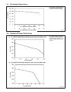
3-1. Weld, Power, And Engine Specifications
Welding
Mode
Weld Output
Range
Rated Welding
Output
Maximum
Open-
Circuit
Voltage
Auxiliary Power Rating Engine
Fuel
Capacity
CC/DC
45 – 500 A
(CC Models)
15 – 500 A
(CC/CV Models)
300 A, 40 Volts DC,
100% Duty Cycle
400 A, 40 Volts DC,
95
Standard
Single-Phase,
4 kVA/kW, 34/17 A,
120/240 V AC,
50/60 Hz
Wis-Con TM-20
Wis
.
Con
25 gal
CV/DC
(CC/CV
Models
Only)
14 – 40 V
400 A, 40 Volts DC,
60% Duty Cycle
500 A, 30 Volts DC,
40% Duty Cycle
56
Full kVA Option*
Single-Phase/Three-Phase,
12/15 kVA/kW, 50/36A,
120/240 VAC, 60 Hz
*In Addition To Standard
4 kVA/kW Auxiliary Power
Water-Cooled,
Three-Cylinder,
38 HP Gasoline
Engine
25 gal
(95 L)