


OM-4405 Page 44
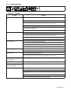
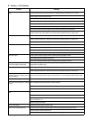
B. Welding – CC/CV Models
Trouble Remedy
No weld output; auxiliary power output
okay.
Place Process/Contactor switch in a Electrode Hot position, or place switch in a Remote position and
connect remote contactor to optional Remote 14 receptacle RC14 (see Sections 4-11 and 6-1).
Check position of Ampere Range switch.
Check position of optional polarity switch.
Reset circuit breaker CB11 (see Section 8-9).
Reset circuit breaker CB5 (see Section 8-9). Check for faulty remote device connected to RC14.
Check and secure connections to Remote 14 receptacle RC14 (see Section 4-11).
Have Factory Authorized Service Agent check connector board PC6 and connections.
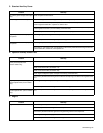
Check fuse F2, and replace if open (see Section 8-9). Have Factory Authorized Service Agent check
brushes and slip rings, field excitation circuit, field current regulator board PC1, and the rotor.
No weld output or auxiliary power output. Disconnect equipment from auxiliary power receptacles during start-up.
Check fuses F1 and F2, and replace if open (see Section 8-9). Have Factory Authorized Service Agent
check integrated rectifier SR1, capacitor C9, field current regulator board PC1, and the rotor.
Have Factory Authorized Service Agent check brushes and slip rings, and field excitation circuit.
Erratic weld output. Check and tighten connections inside and outside unit.
Be sure connection to work piece is clean and tight.
Use dry, properly stored electrodes.
Remove excessive coils from weld cables.
High weld output. Check position of Ampere Range switch and Voltage/Amperage Adjust control.
Check engine speed, and adjust if necessary.
Have Factory Authorized Service Agent check field current regulator board PC1.
Voltage/Amperage control does not
work when welding in Stick mode.
Place Ampere Range switch in lower range. Voltage/Amperage control does not work with Ampere
Range switch in highest range.
Low weld output. Check engine speed, and adjust if necessary.
Check fuses F1 and F2, and replace if open (see Section 8-9). Have Factory Authorized Service Agent
check integrated rectifier SR1, capacitor C9, field current regulator board PC1, and the rotor.
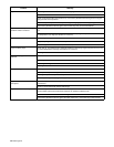
Electrode sticks to the workpiece more
frequently during low voltage (short arc
length) conditions.
Circuit breaker CB4 may be open. CB4 automatically resets when the fault is corrected (see Section 8-9).
Have Factory Authorized Service Agent check transformer T1 and integrated rectifiers SR4 and SR5.
Low open-circuit voltage. Check engine speed, and adjust if necessary.
No remote fine amperage or voltage
control.
Place Voltage/Amperage Adjust switch in Remote position.
Check and secure connections to Remote 14 receptacle RC14 (see Section 4-11).
Repair or replace remote control device.
Constant speed wire feeder does not
work.
Reset circuit breaker CB5 (see Section 8-9).
Check and secure connections to Remote 14 receptacle RC14 (see Section 4-11).
Check voltage requirements of wire feeder. 115 volt output not available through Remote 14 recep-
tacle (see Section 4-11).
Repair or replace wire feeder.
Low CV weld output. Set Ampere Range switch to highest range.
Min or max CV weld output only. Check position of Voltage/Amperage Adjust control and Voltage/Amperage Adjust switch.
Repair or replace remote control device.
Have Factory Authorized Service Agent check field current regulator board PC1.