


OM-4405 Page 30
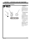
SECTION 7 – OPERATING AUXILIARY EQUIPMENT
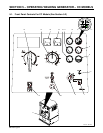
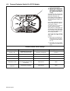
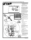
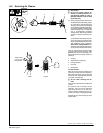
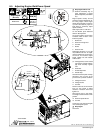
7-1. 120 Volt And 240 Volt Receptacles
191 624-A
2
1 120 V 20 A AC GFCI
Receptacle GFCI1
2 240 V 30 A AC Twistlock
Receptacle RC1
Receptacles supply 60 Hz single-
phase power at weld/power speed.
If a ground fault is detected, GFCI
Reset button pops out and
receptacle does not work. Check
for faulty tools plugged in
receptacle. Press button to reset
GFCI1.
. At least once a month, run en-
gine at weld/power speed and
press test button to verify GFCI
is working properly.
3 Circuit Breaker CB1
4 Circuit Breaker CB2
CB1 protects RC1 and the genera-
tor winding from overload. If CB1
opens, RC1 and GFCI1 do not
work. Place switch in On position to
reset breaker.
CB2 protects GFCI1 from overload.
If CB2 opens, GFCI1 does not
work. Press button to reset breaker.
. If a circuit breaker continues to
open, contact Factory Autho-
rized Service Agent.
. Auxiliary power is not affected
by weld output.
Maximum output is 2.4 kVA/kW
from GFCI1 and 4 kVA/kW from
RC1. Maximum output from all re-
ceptacles is 4 kVA/kW.
EXAMPLE: If 13 A is drawn from
RC1, only 7 A is available at GFCI1:
(240 V x 13 A) + (120 V x 7 A) =
4.0 kVA/kW
1
3
4