


OM-4405 Page 72
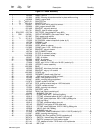
Description
Part
No.
Dia.
Mkgs.
Item
No.
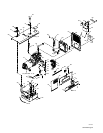
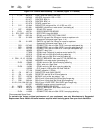
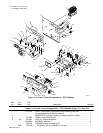
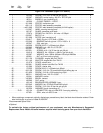
Figure 11-5. Panel, Front w/Components – CC/CV Models (Continued)
Quantity
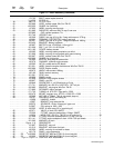
53 097 922 KNOB, pointer .875 dia x .250 ID w/set screws plstc 1. . . . . . . . . . . . . . . . . . . . . . . . . . . . . . . . . . .
54 189 161 HANDLE, switch range 1. . . . . . . . . . . . . . . . . . . . . . . . . . . . . . . . . . . . . . . . . . . . . . . . . . . . . . . . . . . . .
55 010 647 PIN, spring CS .156 x 1.250 1. . . . . . . . . . . . . . . . . . . . . . . . . . . . . . . . . . . . . . . . . . . . . . . . . . . . . . . .
56 097 924 KNOB, pointer 1.625 dia x .250 ID w/set scrws plstc 1. . . . . . . . . . . . . . . . . . . . . . . . . . . . . . . . . . .
193 158 HARNESS, unit weld control – CV (consisting of) 1. . . . . . . . . . . . . . . . . . . . . . . . . . . . . . . . . . . . . . . . .
PLG6 114 063 CONNECTOR, rect univ 084 4p/s 1 row plug cable lkg 1. . . . . . . . . . . . . . . . . . . . . . . . . . . . . . . .
PLG8 193 184 CONNECTOR, rect cinch 30 pin 1. . . . . . . . . . . . . . . . . . . . . . . . . . . . . . . . . . . . . . . . . . . . . . . . . .
PLG13 147 992 CONNECTOR, rect univ 039 10p/s 2 row plug cable 1. . . . . . . . . . . . . . . . . . . . . . . . . . . . . . .
PLG3 158 465 CONNECTOR, rect univ 084 12p/s 3 row plug cable 1. . . . . . . . . . . . . . . . . . . . . . . . . . . . . . . . .
088 731 BUSHING, snap-in nyl .375 ID x .500 mtg hole 1. . . . . . . . . . . . . . . . . . . . . . . . . . . . . . . . . . . . . . . . . . .
135 873 CLIP, conduit convoluted 1/2 in mtg hole 2. . . . . . . . . . . . . . . . . . . . . . . . . . . . . . . . . . . . . . . . . . . . . . . . .
187 654 SEAL, wire univ 12p/s 3 row 1. . . . . . . . . . . . . . . . . . . . . . . . . . . . . . . . . . . . . . . . . . . . . . . . . . . . . . . . . . .
024 103 BLANK, snap-in nyl .750 mtg hole blk 1. . . . . . . . . . . . . . . . . . . . . . . . . . . . . . . . . . . . . . . . . . . . . . . . . . .
120 304 BLANK, snap–in nyl .250 mtg hole black 2. . . . . . . . . . . . . . . . . . . . . . . . . . . . . . . . . . . . . . . . . . . . . . . . .
+ When ordering a component originally displaying a precautionary label, the label should also be ordered. Order
label individually or as part of Label Kit 202 022.
To maintain the factory original performance of your equipment, use only Manufacturer’s Suggested
Replacement Parts. Model and serial number required when ordering parts from your local distributor.
. Hardware is common and
not available unless listed.
802 800
5
6
8
9
24
27
29
30
31
32
1
2
7
11
12
13
14
16
25
28
34
4
3
10
26
16
15
17
18
19
20
21
22
23
28
33
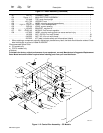
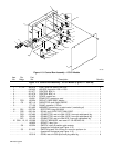
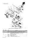
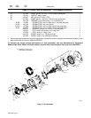
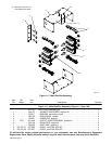
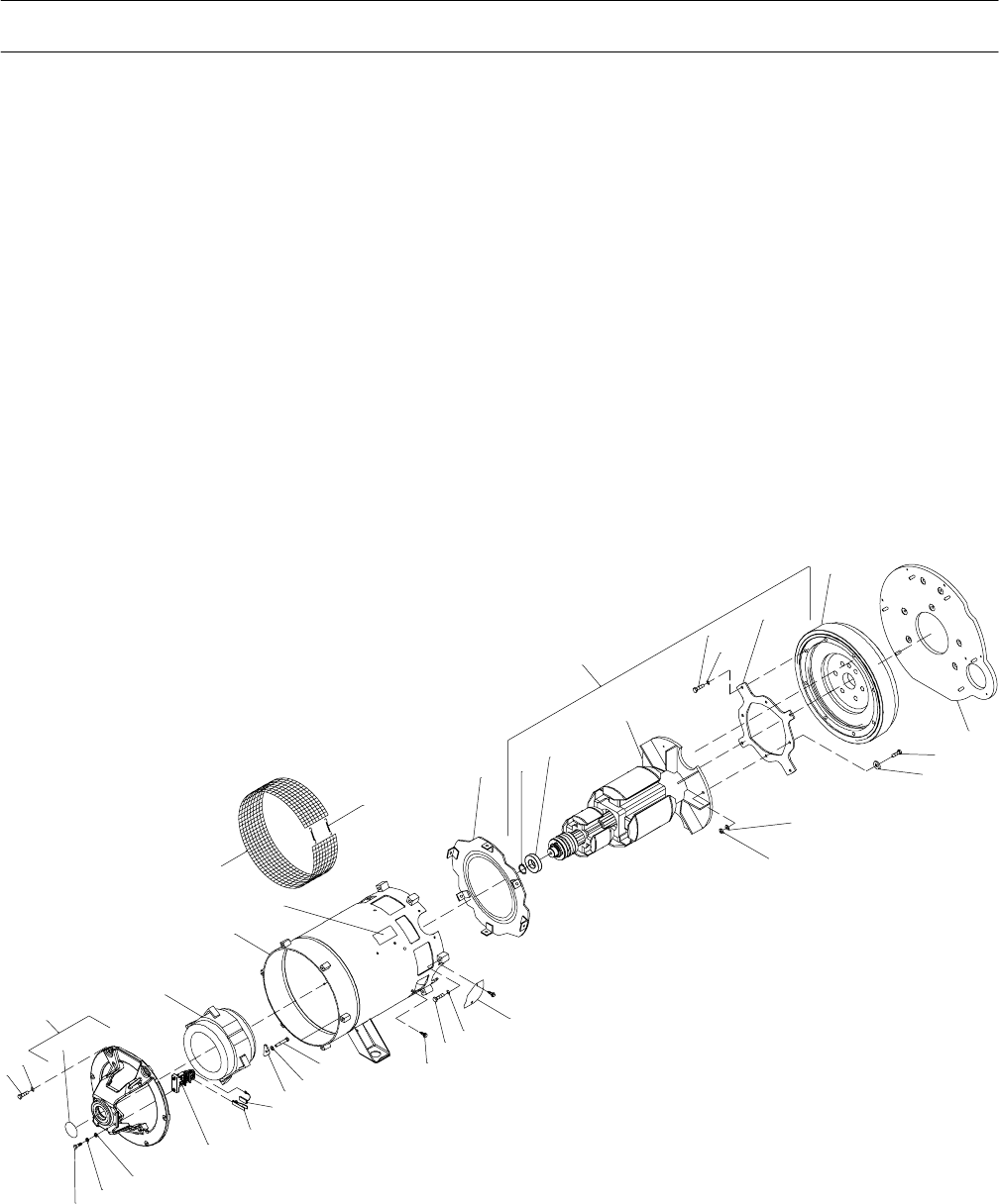
Figure 11-6. Generator