


OM-4405 Page 23
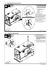
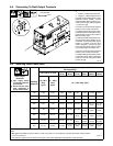
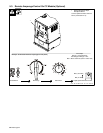
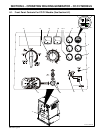
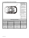
5-2. Description Of Front Panel Controls For CC Models (See Section 5-1)
Engine Starting Controls
1 Magnetic Shutdown Switch
Use switch during start-up to bypass engine
shutdown system. System stops engine if oil
pressure is too low or coolant temperature is
too high.
2 Starting Aid (Engine Choke Control)
Use control to change engine air-fuel mix.
3 Engine Control Switch
Use switch to start engine, select engine
speed, and stop engine.
In Run position, engine runs at weld/power
speed. In Run/Idle position, engine runs at
idle speed at no load and weld speed with load
applied.
To Start:
. If engine does not start, let engine come
to a complete stop before attempting re-
start.
Pull Choke control out. Turn Engine Control
switch to Start while pressing Shutdown
switch. Release Engine Control switch when
engine starts. Continue holding Shutdown
switch until engine indicator lights go out.
Push Choke control in.
To Stop: turn Engine Control switch to Off
position.
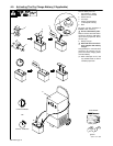
Engine Indicator Lights
4 Battery Charging Light
Light goes on if engine alternator is not charg-
ing battery. Engine continues to run.
Y Stop engine and fix trouble if Battery
Charging light goes on.
5 Engine Temperature Light
Light goes on and engine stops if engine tem-
perature is above 230 ° F (110° C).
Y Stop engine and fix trouble if Engine
Temperature light goes on.
6 Engine Oil Pressure Light
Light goes on and engine stops if oil pressure
is below 5 psi (34 kPa). Light goes on momen-
tarily during start-up but goes out when en-
gine reaches normal oil pressure.
Y Stop engine and fix trouble if Engine
Oil Pressure light stays on after start-
up.
7 Fuel Light
Fuel light is not active on this model.
8 Engine Hour Meter
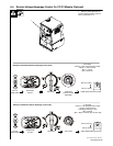
Engine Gauges
. To read gauges and engine indicator
lights with engine off, turn Engine Control
switch to Run/Idle and press Magnetic
Shutdown switch (see Section 8-10).
9 Fuel Gauge
Use gauge to check fuel level.
To check fuel level when engine is not run-
ning, turn Engine Control switch to Run/Idle
position and press Magnetic Shutdown
switch.
10 Battery Voltmeter (Optional)
Use gauge to check battery voltage and moni-
tor the engine charging system. The meter
should read about 14 volts dc when the en-
gine is running, and about 12 volts dc when
the engine is stopped.
11 Engine Coolant Temperature Gauge
(Optional)
Normal temperature is 180 - 203° F (82 - 95°
C). When equipped with gauge option, engine
stops if temperature exceeds 220° F (104° C).
12 Engine Oil Pressure Gauge (Optional)
Normal pressure is 30 – 80 psi (207 – 552
kPa). When equipped with gauge option, en-
gine stops if pressure is below 10 psi (69
kPa).
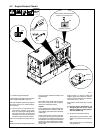
Weld Controls
. Max OCV Control Circuit: This unit has
a max OCV control circuit that resets Am-
perage Adjust control R1 to maximum
when the arc breaks. When an arc is
struck, weld output control returns to the
R1 front panel or combination front panel/
remote control setting. The Amperage
Adjust control adjusts amperage only
when welding and does not adjust open-
circuit voltage.
The max OCV circuit is disabled when
the Stick/TIG Selection switch is in
Scratch Start TIG position (see item 15).
13 Ampere Range Switch
Y Do not switch under load.
Use switch to select weld amperage range.
For most welding applications, use lowest
amperage range possible to help prevent arc
outages.
14 Amperage Adjust Control
Control adjusts amperage within range se-
lected by Ampere Range switch. Weld output
would be about 153 A DC with controls set as
shown (50% of 100 to 205 A).
. The numbers around the control are for
reference only and do not represent an
actual percentage value.
15 Stick/TIG Selection Switch
Use switch to disable the max OCV circuit
and the arc drive (dig) circuit for scratch start
TIG welding (see max OCV note under Weld
Controls).
When switch is in the Stick position, the max
OCV circuit resets Amperage Adjust Control
R1 to maximum when the arc breaks.
Also in the Stick position, the arc drive (dig)
circuit provides additional amperage during
low voltage (short arc length conditions) to
prevent “sticking” electrodes.
When switch is in Scratch Start TIG position,
the max OCV and arc drive (dig) circuits are
disabled and OCV changes when the control
is adjusted.
16 Amperage Adjust Switch And Remote
Amperage Adjust Receptacle
Connect optional remote control to RC13
(See Section 4-10). Use switch to select front
panel or remote amperage control. For re-
mote control, place switch in Remote position
and connect remote control to Remote Am-
perage Adjust receptacle RC13 (see Sec-
tions 4-10 and 5-3).
17 Polarity Switch (Optional)
Y Do not switch under load.
Use switch to change weld output. Select ei-
ther DC Electrode Positive (DCEP) or DC
Electrode Negative (DCEN).
Weld Meters
18 DC Voltmeter (Optional)
Voltmeter displays voltage at the weld output
terminals, but not necessarily the welding arc
due to resistance of cable and connections.
19 DC Ammeter (Optional)
Ammeter displays amperage output of the
unit.