


OM-4405 Page 74
. Hardware is common and
not available unless listed.
802 279-A
1
2
3
4
6
5
7
8
9
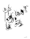
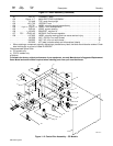
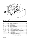
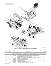
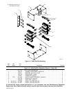
Figure 11-7. Main Rectifier Assembly
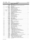
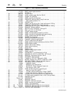
Description
Part
No.
Dia.
Mkgs.
Item
No.
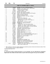
Figure 11-7. Main Rectifier Assembly (Figure 11-1 Item 100)
Quantity
201 747 RECTIFIER (consisting of) 1. . . . . . . . . . . . . . . . . . . . . . . . . . . . . . . . . . . . . . . . . . . . . . . . . . . . . . . . . . . .
1 188 137 CONNECTION BOARD, rectifier AC 1. . . . . . . . . . . . . . . . . . . . . . . . . . . . . . . . . . . . . . . . . . . . . . . . .
2 188 517 BUS BAR, connection board 3. . . . . . . . . . . . . . . . . . . . . . . . . . . . . . . . . . . . . . . . . . . . . . . . . . . . . . . .
3 188 135 ENCLOSURE, rectifier 2. . . . . . . . . . . . . . . . . . . . . . . . . . . . . . . . . . . . . . . . . . . . . . . . . . . . . . . . . . . . .
4 134 201 STAND-OFF, support 3. . . . . . . . . . . . . . . . . . . . . . . . . . . . . . . . . . . . . . . . . . . . . . . . . . . . . . . . . . . . . .
5 PC3 201 449 CIRCUIT CARD ASSEMBLY, protection 1. . . . . . . . . . . . . . . . . . . . . . . . . . . . . . . . . . . . . . . .
6 188 136 INSULATOR, heat sink 8. . . . . . . . . . . . . . . . . . . . . . . . . . . . . . . . . . . . . . . . . . . . . . . . . . . . . . . . . . . . .
7 188 493 HEAT SINK, rectifier al 2. . . . . . . . . . . . . . . . . . . . . . . . . . . . . . . . . . . . . . . . . . . . . . . . . . . . . . . . . . . . .
8 D3, D5, D7 037 956 DIODE, rect 275A 300V SP 3. . . . . . . . . . . . . . . . . . . . . . . . . . . . . . . . . . . . . . . . . . . . .
9 D2, D4, D6 037 957 DIODE, rect 275A 300V RP 3. . . . . . . . . . . . . . . . . . . . . . . . . . . . . . . . . . . . . . . . . . . . .
To maintain the factory original performance of your equipment, use only Manufacturer’s Suggested
Replacement Parts. Model and serial number required when ordering parts from your local distributor.