


OM-4405 Page 14
SECTION 4 – INSTALLATION
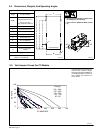
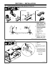
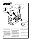
4-1. Installing Welding Generator (See Sections 4-2 And 4-3)
install2 1/01 – Ref. 800 652 / Ref. 800 477-A / 158 936-A / 0854
1
2
Electrically bond generator frame to
vehicle frame by metal-to-metal
contact.
GND/PE
3
4
Y Always securely fasten
welding generator onto
transport vehicle or trailer
and comply with all DOT and
other applicable codes.
Y Always ground generator
frame to vehicle frame to pre-
vent electric shock and static
electricity hazards.
1 Generator Base
2 Metal Vehicle Frame
3 Equipment Grounding
Terminal
4 Grounding Cable
Use #10 AWG or larger insulated
copper wire.
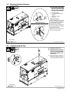
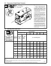
Y If unit does not have GFCI re-
ceptacles, use GFCI-
protected extension cord.
2
OR
18 in
(460 mm)
18 in
(460 mm)
18 in
(460 mm)
18 in
(460 mm)
18 in
(460 mm)
OR
Movement Airflow Clearance Location
Grounding
OR
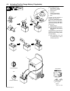
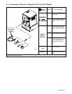
4-2. Using Lifting Eye
Ref. 802 729
1 Lifting Eye
2 Nut
3 Carriage Bolt
Raise lifting eye until it snaps in
place. Lower lifting eye when not
needed.
. To lock the lifting eye in the up-
right position, insert a 3/8-16 x
1-1/2 in carriage bolt through
slot in bracket and secure with
nut (bolt and nut not supplied).
Tools Needed:
2
1
3