


OM-4405 Page 37
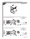
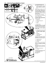
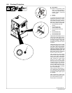
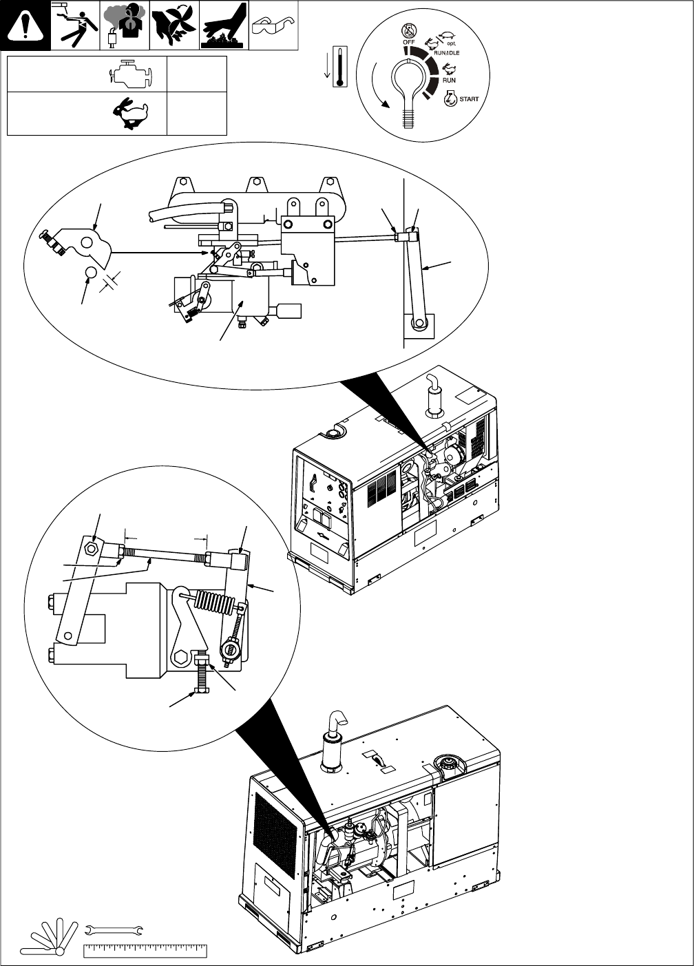
8-5. Adjusting Engine Weld/Power Speed
802 731 / 802 780 / Ref. 801 179 / Ref. 800 161
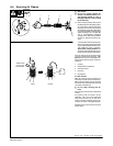
Y Stop engine and let cool.
. Governor sensitivity may re-
quire adjustment if engine
speed is adjusted (see Section
8-7).
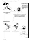
Engine speed is factory set and
should not require adjustment. Af-
ter tuning engine, check engine
speed with tachometer or frequen-
cy meter. See table for proper no
load speed. If necessary, adjust
speed as follows:
Start engine and run until warm.
On CC Models, place Stick/TIG
switch in Stick position.
On CC/CV models, turn Process/
Contactor switch to Stick – Elec-
trode Hot position.
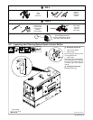
1 Socket Nut
2 Governor Linkage Rod
3 Lock Nut
4 Socket
5 Governor Arm
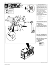
Rod length should be 3-1/4 in (83
mm) between lock nuts. To adjust,
remove socket from arm and loos-
en lock nut. Turn socket to adjust
length. Tighten nut and reattach
socket to arm.
. If linkage binds, loosen socket
nuts and turn sockets until link-
age works smoothly. Tighten
nuts.
6 Carburetor
7 Throttle Stop Plate
8 Throttle Stop
Clearance between plate and stop
should be 1/16 in (1.6 mm). To ad-
just clearance, proceed as follows:
9 Linkage Pivot Arm
10 Linkage Socket
11 Lock Nut
Remove socket at arm and loosen
lock nut. Turn socket to adjust
clearance. Reattach socket and
tighten nut.
Start engine and run until warm.
Turn Engine Control switch to Run
position.
12 Governor Speed Screw
13 Lock Nut
Loosen nut. Turn screw until engine
runs at weld/power speed.
Y Stop engine.
Close door.
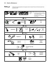
Tools Needed:
3/8, 7/16 in
2
3
4
5
6
7
8
9
1011
12
13
3-1/4 in
(83 mm)
1/16 in
(1.6 mm)
1
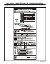
RPM (Hz)
Engine Speed
(No Load)
Weld/Power
1850 (61.7)
Maximum