


TM-499 Page 24
SECTION 9 − EXPLANATION OF ELECTRICAL PARTS
elect_parts 7/04
9-1. Safety Precautions − Read Before Using This Guide
Y WARNING: ELECTRIC SHOCK can kill.
D Disconnect input power or stop engine before servicing.
D Do not touch live electrical parts.
D Do not operate machines with covers removed.
D Have only qualified persons install, use, or service equipment.
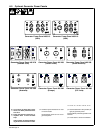
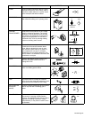
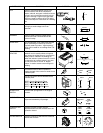
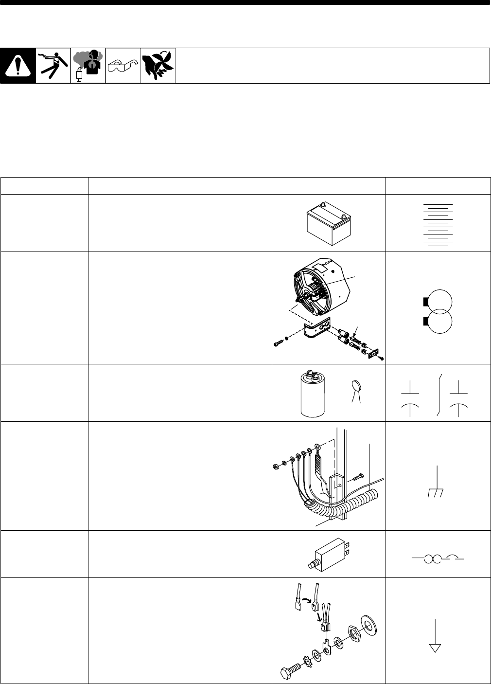
PART NAME FUNCTION PICTURE CIRCUIT SYMBOL
BATTERY A source of DC voltage. Typically used in
Engine Driven equipment.
+
BRUSHES/SLIP
RINGS
Components that allow electrical connections
between stationary and rotating contacts.
SLIP
RINGS
BRUSHES
CAPACITOR A device that stores electrical energy. Large
capacitors or a “bank” of capacitors can be
used to “smooth out” the DC welding arc in a
MIG welding power source. Smaller “disk”
capacitors can be used for HF protection.
C1
C1
POLARIZED NON-POL.
+
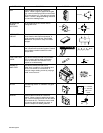
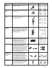
CHASSIS The green ground wire of a primary cord is
connected to the machine frame (chassis) for
safety. Also, you may find many “HF bypass”
capacitors connected to chassis to reduce
High Frequency interference. Expect to see
this symbol used numerous times in circuit
diagrams. The picture shown here is from an
Engine Drive where several wires including
the battery are connected to the chassis.
CIRCUIT BREAKER A protection device that breaks a circuit when
current levels exceed its rating. Unlike a fuse
that needs to be replaced when blown, a
circuit breaker can be reset.
CB1
CIRCUIT COMMON When many wires are connected together,
rather than showing all the “lines” and “dots”,
this symbol may appear on the circuit. Look
for other Circuit Common symbols on a
circuit diagram. For instance, say 10 symbols
are found on a circuit, this means all ten
points are electrically tied together.