


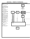
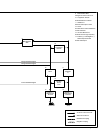
TM-499 Page 26
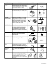
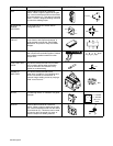
PART NAME CIRCUIT SYMBOLPICTUREFUNCTION
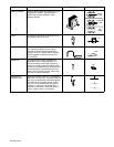
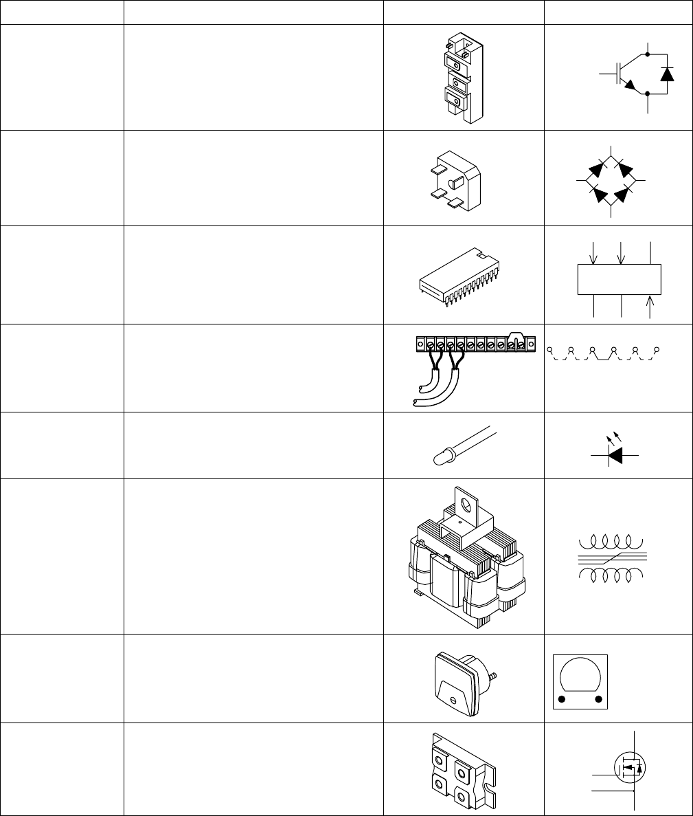
IGBT A device that is used as an “electronic
switch”. When a signal is applied to the gate
(G), current is allowed to flow from the emitter
(E) to the collector (C). This device is typically
used in “Inverter” designed welding machines
to control the welding output.
C1
G1 (B1)
E1
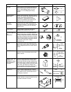
INTEGRATED
BRIDGE
RECTIFIER
An arrangement of four diodes used to
change AC to DC.
AC
AC
−
+
AC
AC
+
_
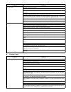
INTEGRATED
CIRCUIT
IC’s often called “chips” provide a complete
circuit function with inputs and outputs. A
good example would be the “Pulse Width
Modulation” chip used in many wire feeder
designs.
U1
JUMPER LINK Usually, the jumper link is a piece of brass
that connects two terminals together. Dashed
lines indicate possible locations for other
jumper links.
TE1
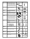
LIGHT EMITTING
DIODE
This device usually referred to by its initials
LED is used to tell you when a particular
circuit is activated. This function is very
helpful for troubleshooting.
D1
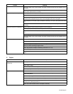
MAGNETIC
AMPLIFIER
This device usually referred to as a
“Mag-Amp” is made up of coil windings and
an iron core similar to a transformer. It
controls a large welding current by varying a
small “control current”.
MA1
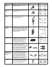
METER A measuring device. A “voltmeter” is a good
example.
V
V = voltmeter
A = ammeter
HM = hour
meter
MOSFET A device that is used as an “electronic
switch”. When a signal is applied to the gate
(G), current is allowed to flow from the source
(S) to the drain (D). This device can be used
to control a relay, the speed of a motor, or
even the output of a welding machine.
D
G
AS
S