


TM-499 Page 31
SECTION 10 − TROUBLESHOOTING
10-1. Troubleshooting Tables
A. Welding
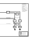
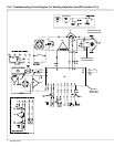
. See Section 10-2 for test points and
values and Section 13 and following
for parts location.
Trouble Remedy
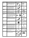
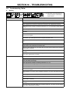
No weld output. Check weld connections.
Disconnect equipment from receptacles when starting unit.
Check resistance and connections of resistor R3; R3 is 20 ohms ±5%. Replace R3 if necessary.
Check engine speed, and adjust if necessary (see Section 7-4 or 7-5). Output stops if engine speed is
too low.
Check slip rings, and install new brushes if necessary (see Section 10-7).
Check resistance and connections of Current Control R1; R1 is 0 to 1000 ohms ±10%. Replace R1 if
necessary.
Check control board PC1 and connections, and replace if necessary (see Section 10-5). PC1 LED lights
when board is energized.
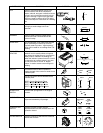
Check engine lamp coil and connections, and replace coil if necessary. Lamp coil supplies power to con-
trol board PC1. PC1 LED lights when board is energized (see Section 10-5).
Check capacitor C1 for a short or open, and replace if necessary. If C1 is open, also replace circuit board
PC1.
Check integrated rectifier SR1, and replace if necessary.
Check diodes in main rectifier SR2, and replace if open.
Disconnect stator weld leads from main rectifier SR2, and check continuity between stator weld leads.
Replace stator if necessary.
Disconnect leads 3 and 4 from brushes, and check continuity across slip rings. Replace rotor if
necessary.
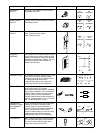
Disconnect stator exciter leads (black) from integrated rectifier SR1, and check continuity between
exciter leads. Replace stator if necessary.
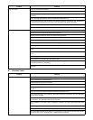
Low weld output. Check Current Control R1 setting.
Check throttle lever setting.
Check weld cable size and length.
Check engine speed, and adjust if necessary (see Section 7-4 or 7-5).
Service air cleaner according to engine manual.
Check slip rings, and install new brushes if necessary (see Section 10-7).
Check control board PC1 and connections, and replace if necessary (see Section 10-5). PC1 LED lights
when board is energized.
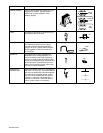
Check capacitor C1 for a short or open, and replace if necessary. If C1 is open, also replace circuit board
PC1.
Check integrated rectifier SR1, and replace if necessary.
Check diodes in main rectifier SR2, and replace if open.
Disconnect stator weld leads from main rectifier SR2, and check continuity between stator weld leads.
Replace stator if necessary.
Disconnect leads 3 and 4 from brushes, and check continuity across slip rings. Replace rotor if
necessary.
Disconnect stator exciter leads (black) from integrated rectifier SR1, and check continuity between
exciter leads. Replace stator if necessary.