


TM-499 Page 45
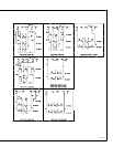
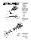
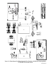
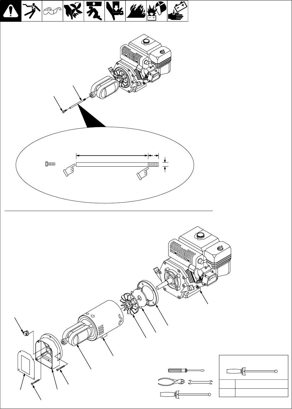
11-2. Removing Rotor And Reassembling Generator
802 524 / 802 509
Y Do not damage rotor or sta-
tor windings during this pro-
cedure.
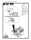
To remove rotor:
1 Rotor Removal Tool
(Customer Supplied)
2 Screw, 7/16-14 x 1-1/4
(Customer Supplied)
Remove rotor thru-bolt.
Make rotor removal tool from
stress-proof steel rod according to
specifications. Slide threaded end
of tool through rotor. Tighten tool in
engine shaft. Turn screw into rotor
while lightly tapping rotor lamina-
tions. (turning screw into rotor
forces rotor off engine shaft.)
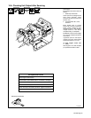
Reassembly
3 Brushholder Assembly
4 Generator End Panel
5 Bearing Carrier
6 Rotor Assembly
7 Stator Assembly
8 Generator Fan
9 Generator Guard
10 Engine Adapter
11 Engine
Reinstall engine and generator
parts using torque values in table.
Reconnect all leads. Use cable ties
to secure leads in wiring harness
and away from moving or hot parts.
Reinstall cover.
A 95 in lb (10.7 N
.
m)
B 205 in lb (23.1 N
.
m)
Torques:
Tools Needed:
3
4
5
6
7
8
9
10
11
A
B
1 in
(25.4 mm)
5/16 in
(8 mm)
7-1/2 in
(191 mm)
1
2
Cut screwdriver
slot in end of rod.
Removing Rotor
Reassembling Generator
24 threads
per inch