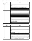
Categories
- Automotive
- Baby Care
- Car Audio & Video
- Cell Phone
- Communications
- Computer Equipment
- Fitness & Sports
- Home Audio
- Household Appliances
- Kitchen Appliances
- Laundry Appliances
- Lawn & Garden
- Marine Equipment
- Musical Instruments & Equipment
- Outdoor Cooking
- Personal Care
- Photography
- Portable Media
- Power Tools
- TV and Video
- Video Game
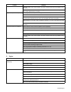
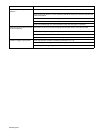
Top Automotive Device Types
Top Baby Care Device Types
Top Car Audio & Video Device Types
Top Cellphone Device Types
Top Communications Device Types
Top Computer Device Types
Top Fitness Device Types
Top Home Audio Device Types
Top Household Appliance Device Types
Top Kitchen Appliance Device Types
Top Laundry Appliance Device Types
Top Lawn & Garden Device Types
Top Marine Equipment Device Types
Top Musical Instrument Device Types
Top Outdoor Cooking Device Types
Top Personal Care Device Types
Top Photography Device Types
Top Portable Media Device Types
Top Power Tools Device Types
Top TV and Video Device Types
Top Videogame Device Types
A SERVICE OF