


TM-499 Page 43
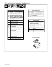
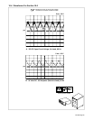
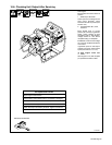
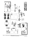
10-8. Checking Unit Output After Servicing
ST-802 524
Start engine.
Move throttle control lever to 60 Hz
position.
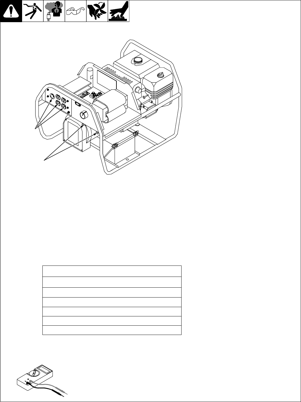
1 Weld Output Terminals
Check open-circuit voltage across
weld output terminals. There
should be 68 volts dc present (see
Section 10-2).
2 AC Receptacles RC1, RC2,
And RC3
Move throttle lever to correct
position (50 or 60 Hz) for generator
power. Check voltage at each
receptacle. With no load applied,
voltage should be 10% above
receptacle rating on nameplate.
EXAMPLE: Correct no load voltage
for a 120 volt receptacle should be
132 volts ac.
If generator power or weld output
voltage is incorrect, adjust engine
speed (see Section 7-4 or 7-5).
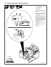
Y Stop engine. Close fuel
valve.
Allow engine to cool, and complete
pre-operational checks in table.
1
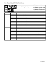
Test Equipment Needed:
Pre-Operational Checks
Wipe engine surfaces clean.
Check labels; replace labels that are unreadable or damaged.
Check and correct any fluid leaks.
Clean weld output and battery terminals. Tighten connections.
Clean outside of entire unit.
Check fuel and oil (see Section 4-4 or 4-5).
2