


TM-499 Page 33
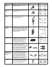
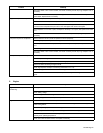
Trouble Remedy
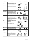
Disconnect leads 3 and 4 from brushes, and check continuity across slip rings. Replace rotor if
necessary.
Disconnect stator exciter leads (black) from integrated rectifier SR1, and check continuity between
exciter leads. Replace stator if necessary.
High power output at ac receptacles. Check engine speed, and adjust if necessary (see Section 7-4 or 7-5).
Move throttle lever to Run (use 50 Hz position for 50 Hz equipment).
Check control board PC1 and connections, and replace if necessary (see Section 10-5). Replace PC1
if shorted across receptacle RC4 pins 4 and 6. PC1 LED lights when board is energized.
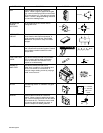
Check capacitor C1 for a short or open, and replace if necessary. If C1 is open, also replace circuit board
PC1.
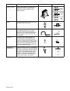
Disconnect leads 3 and 4 from brushes, and check continuity across slip rings. Replace rotor if
necessary.
Low power output at ac receptacles. Move throttle lever to Run (use 60 Hz position for 60 Hz equipment).
Check engine speed, and adjust if necessary (see Section 7-4 or 7-5).
Check capacitor C1 for a short or open, and replace if necessary. If C1 is open, also replace circuit board
PC1.
Check integrated rectifier SR1, and replace if necessary.
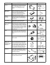
Disconnect leads 3 and 4 from brushes, and check continuity across slip rings. Replace rotor if
necessary.
Erratic power output at ac receptacles. Check fuel level.
Check receptacle wiring and connections.
Check throttle/governor linkage for smooth, non-binding operation.
Service air cleaner according to engine manual.
Check engine speed, and adjust if necessary (see Section 7-4 or 7-5).
Check slip rings, and install new brushes if necessary (see Section 10-7).
Check control board PC1 and connections, and replace if necessary. PC1 LED lights when board is ener-
gized.
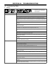
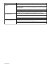
C. Engine
Trouble Remedy
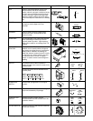
Engine will not crank (electric-start
models only).
Reset ignition circuit breaker.
Check battery voltage.
Check battery connections and tighten if necessary.
Check engine ignition circuit, and replace components if necessary.
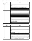
Engine will not start. Check fuel level (see Section 4-4 or 4-5).
Open fuel valve (see Section 4-4 or 4-5). Close fuel valve before moving unit or carburetor may flood and
make starting difficult.
Check battery voltage (electric-start models only).
Check battery connections and tighten if necessary (electric-start models only).
Check oil level (see Section 4-4 or 4-5). Engine stops if oil level is too low. Refill crankcase with proper
viscosity oil for operating temperature.
Check low oil level shutdown switch, and replace if necessary.