


TM-499 Page 46
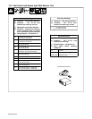
SECTION 12 − ELECTRICAL DIAGRAMS
. The circuits in this manual can be used for troubleshooting, but there might be minor circuit differences from your machine. Use circuit
inside machine case or contact distributor for more information.
The following is a list of all diagrams for models covered by this manual.
Model Serial Or Style Number
Circuit
Diagram
Wiring
Diagram
Welding Generator LA124002 and following (Kohler)
LA347885 and following (Honda)
197 857-E 197 858-C
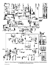
Generator Power Panels LA124002 and following (Kohler)
LA347885 and following (Honda)
201 026-A
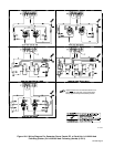
Circuit Board PC1 LA124002 and following (Kohler)
LA033425 and following (Honda)
198 222
Circuit Board PC2 LA124002 and following (Kohler)
KH467216 and following (Honda)
SA-148 611-A
The circuits for Honda-powered units were implemented prior to the effective date
of this manual.
NOTE
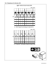
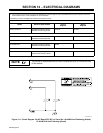
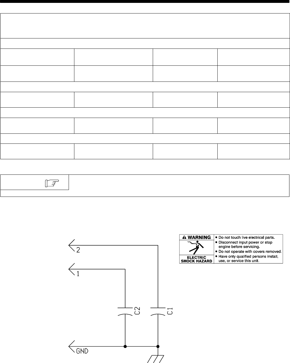
SA-148 611-A
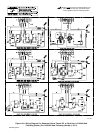
Figure 12-1. Circuit Diagram For HF Board PC2 Eff. w/ Serial No. LA124002 And Following (Kohler)
Or KH467216 And Following (Honda)