


TM-499 Page 30
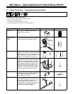
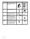
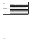
PART NAME CIRCUIT SYMBOLPICTUREFUNCTION
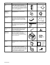
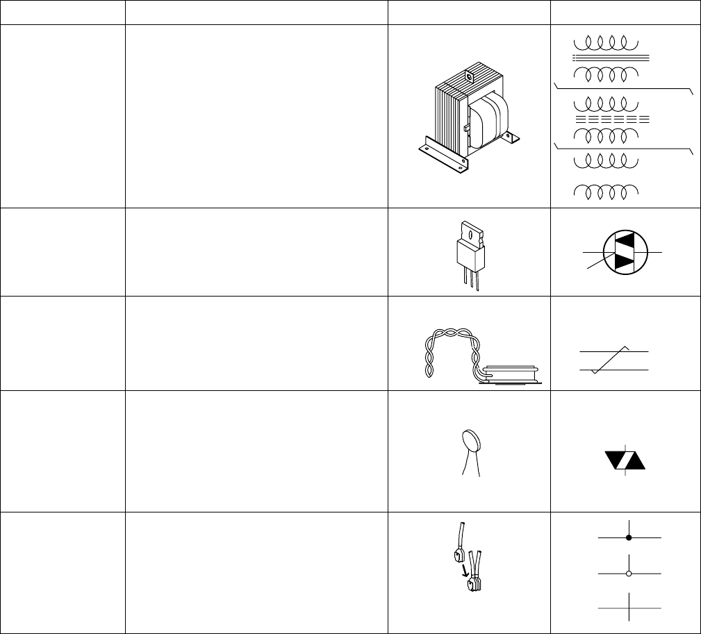
TRANSFORMER A device that changes AC voltage from one
magnitude to another. Typically used to
reduce high primary voltages to lower
welding voltages.
T1
T1
T1
IRON
CORE
AIR
CORE
FERRITE
CORE
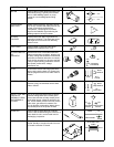
TRIAC An electronic AC switch. It is turned on by a
gate signal similar to an SCR.
Q1
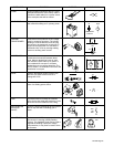
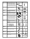
TWISTED WIRE Wires are twisted to prevent “electrical noise”
from interfering with the circuit. A good
example is the red and white gate leads
going to an SCR. Typically, these wires are
twisted together to help prevent the SCR
from misfiring.
RED
WHT
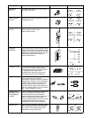
VARISTOR A protection device whose resistance is
dependent on the voltage applied to it. In
normal operation it has a high resistance;
however, a surge of voltage (voltage spike)
will cause its resistance to go way down and
absorb the spike. These devices are most
often found in rectifying circuits, where they
are used to protect the diodes.
VR1
WIRES WITH
CONNECTION
When lines (wires) cross on a circuit diagram
and there is a “black dot”, this means that the
two wires are electrically connected together.
The method of connection (bolted, friction
lugs, etc.) is not indicated with this symbol.
However, a “white dot” indicates that the
method of connection is a terminal strip. Of
course, no dot means no connection.