


TM-499 Page 41
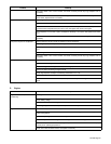
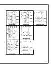
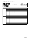
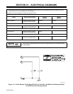
10-6. Control Board PC1 Test Point Values
PC1 Voltage Readings
a) Tolerance −
±10% unless
specified
b) Condition − no load; throttle
lever in 60 Hz position
c) Reference − to circuit common
(RC4-7) unless noted
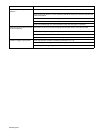
Receptacle Pin Value
RC4 1 18 volts ac input with respect to pin 2
2 18 volts ac input with respect to pin 1
3 +50 volts dc output with respect to pin 4
4 −50 volts dc output with respect to pin 3
5 +200 volts dc input with respect to pin 6
6 Circuit common
7 Circuit common (shield) for shunt input
8 Shunt negative (circuit common)
9 Shunt positive (less than 1 volt dc input with respect to pin 8 with 100 ampere, 25 volt weld load
RC5 1 0 volts dc
2 +15 volts dc input
3 Circuit common
4 +10 volts dc output with respect to pin 6
5 0 to +10 volts dc input from min. to max. of Current Control R1 with respect to pin 6
6 Circuit common
7 Weld feedback input; same as negative (−) weld output terminal voltage
8 0 volts dc
9 0 volts dc when engine speed is greater than 2800 rpm