


INSTALLING OPTIONS
EATON Powerware
®
9155 Parallel UPS (8–15 kVA) User’s Guide S 164201592 Rev C www.powerware.com
26
NOTE If you are installing another X-Slot card, be sure to install the Powerware Hot Sync
CAN Bridge Card in X-Slot 2.
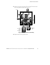
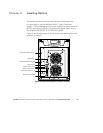
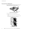
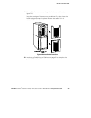
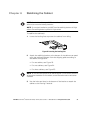
4. Loosely install the Powerware Hot Sync CAN Bridge Card into an
open X-Slot on the front of the UPS. You may want to remove the
terminal block from the CAN Bridge Card for better wiring access.
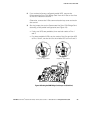
5. Strip shielded, four-wire, twisted -pair wire for CAN Bridge Card
wiring. Recommended wire size is 18 AWG maximum.
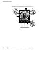
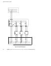
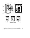
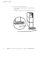
6. Install the CAN Bridge Card wiring between each UPS (see
Figure 19). Be sure to check correct polarity for Pins 8 and 9:
S Connect SHIELD Pin 10 on all cards together.
S Connect CAN H Pin 9 and CAN L Pin 8 (twisted pair) on all cards
together.
S Connect COM Pin 4 and NC Pin 3 (twisted pair) on all cards
together.
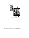
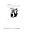
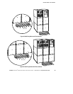
7. Install the pull-chain wiring between the CAN Bridge Card and
Signal Input 2 on each UPS and daisy chain the wiring to each UPS.
Be sure to check correct polarity (see Figure 19):
S Connect COM Pin 4 to Signal Input 2 Pin 1 on each UPS.
S Connect NC Pin 3 to Signal Input 2 Pin 2 on each UPS.
CAUTION
If polarity or wiring is not correct, the parallel system does not operate normally. For
example, when shutting down one UPS, the remaining UPS transfers the load to bypass
instead of supporting the load. Verify all CAN Bridge Card wiring is correct for proper
operation.
NOTE Signal Input 2 can still be used for building alarms; it is automatically rerouted to
the CAN Bridge Card.