


13
Assembly
WARNING: This tool is heavy. To reduce the risk of
back injury, get help whenever you have to lift the tool.
Cabinet and Motor Mount Assembly
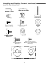
1. From the hardware pack find the following:
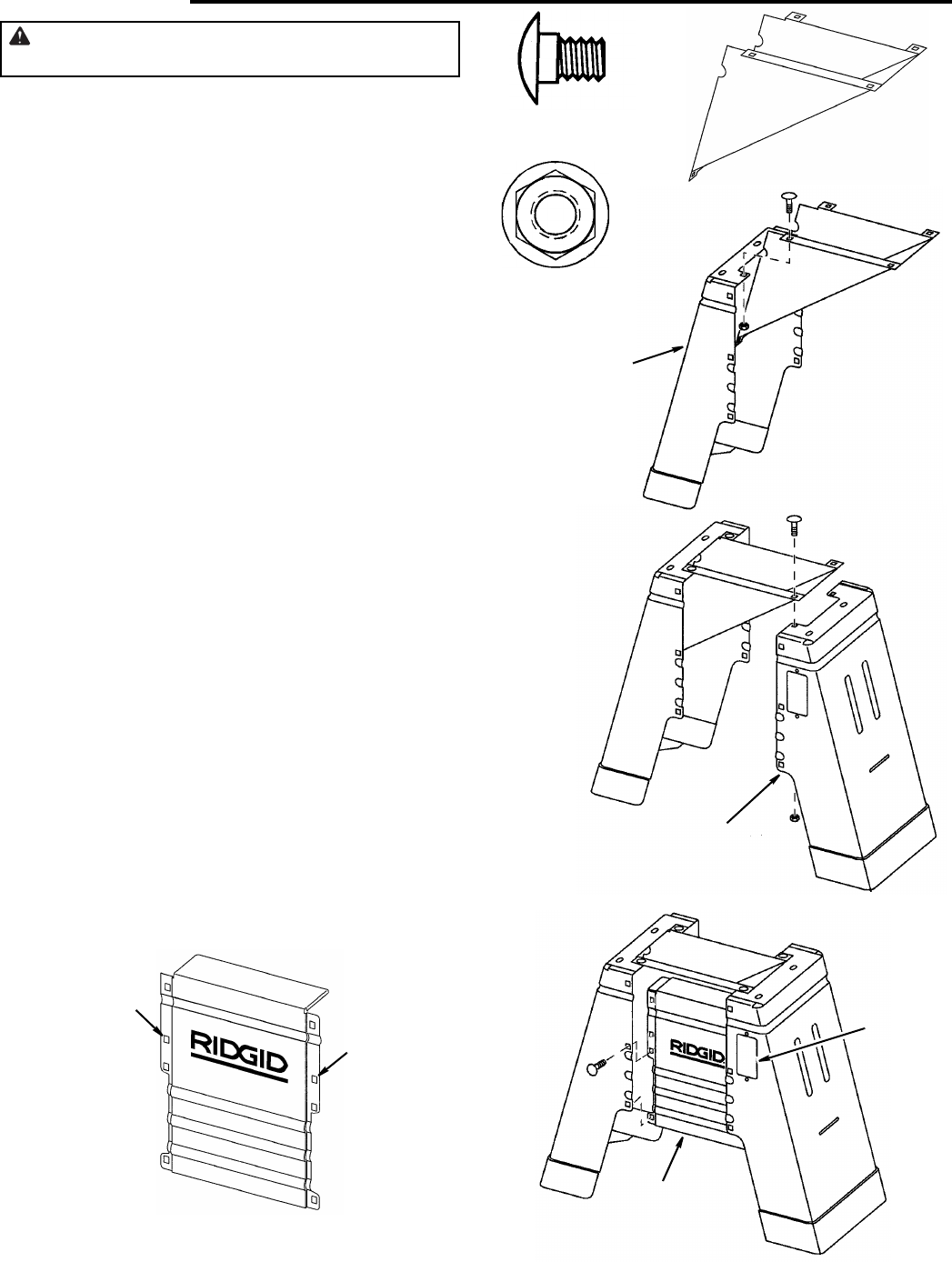
6 Carriage Head Bolts 5/16-18 x 1/2"
6 Serrated Flange Hex Nut 5/16
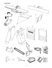
From among the loose parts find the following:
Left Panel Side
Right Panel Side
Motor Mount
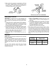
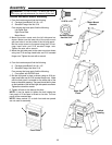
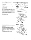
2. Mount the motor mount onto the left side panel as
shown. Make sure the lower tab of the motor mount
with two holes is on the inside of the left side panel .
Bolt the motor mount to the panel using the 5/16 car-
riage head bolts and 5/16 serrated flange nuts.
Tighten the nuts with a wrench.
3. Mount the right side panel to the motor mount as shown
using two 5/16 carriage head bolts and 5/16 serrated
flange nuts. Tighten the nuts with a wrench.
4. From the hardware pack find the following:
6 Carriage Head Bolts 5/16-18 x 1/2"
6 Serrated Flange Hex Nuts 5/16
From among the loose parts find the following:
1 Front panel with RIDGID label
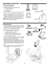
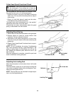
5. Bolt the front panel in place as shown using six 5/16 car-
riage head bolts and six 5/16 serrated flange nuts. Make
sure the front panel is mounted on the same side of the
base as the switch opening. The panel should bolt in place
on the backside of the left and right side panels as shown.
Tighten the nuts with a wrench.
6. Tighten all bolts on the base at this time.
NOTE: It may be easier to tighten the bolt holding the
front panel on if the base is turned on its side. The rear
panel will be mounted later.
NOTE: Holes marked “A” on both front and rear panels
are not used for assembly .
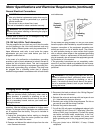
Right Side
Panel
Carriage Head Bolt
5/16-18 x 1/2"
Serrated Flange
Hex Nut 5/16
Motor Mount
Bracket
Left Side
Panel
Cabinet Front
Switch
Opening
Front Panel
A
A