


19
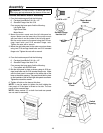
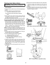
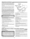
Cutter Head Guard Functional Check
WARNING: Cutter guard helps provide protection
over the cutterhead. It must always be in place and
functioning properly to prevent serious personal injury.
With the power off and the switch key removed, check
the guard to make sure it is functioning properly.
• Position the fence to the rear of the bed for maximum
width of cut. Do not position fence beyond rear edge of
cutter knives.
• Pass a 1/4 inch thick piece of wood over the cutter-
head between the guard and the fence.
The guard must return automatically to a “rest position”
against the fence when free of the wood.
If guard does not return automatically, adjust the guard
spring, as described in the next section.
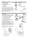
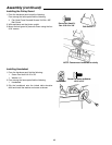
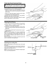
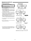
Adjusting Guard Spring
1. Remove the pan head screw from bottom of the guard post.
2. Remove tension on guard by turning tension knob
clockwise. Pull up on guard to remove.
3. Add tension to the cutter head guard in 1/2 turn incre-
ments by turning the tension knob and reinserting the
guard post.
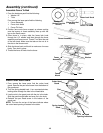
4. Repeat Cutter Head Guard Functional check as previ-
ously described.
NOTE: Do not overtighten the spring. Overtightening
may cause premature spring or guard breakage. If the
guard or spring breaks or malfunctions, do not use the
tool. Replace the defective parts before the tool is put
back in service.
When the adjustment is complete, reinstall the pan head
screw in the bottom of the guard post.
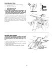
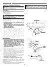
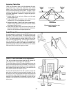
Adjusting the Leveling Feet
Move the jointer/planer to the location where it will reside
during use.
Level the cabinet, loosen the nut and adjust leveling feet
up or down as needed. Adjust all four leveling feet if nec-
essary and then tighten the nut.
NOTE: These levelers are not intended for height adjust-
ment, only leveling adjustment.
Pan Head Screw
Spring Loaded
Knob
Leveling Foot
3/8-16 Hex Nut
Cabinet
˜