


26
Alignments (continued)
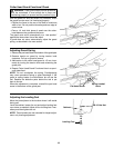
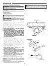
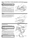
To set the fence to 90° simply pivot the fence slightly for-
ward of 90°, flip the 90° stop bar into place and pivot the
fence back until it contacts the 90° stop and lock into
place. The fence may need to be repositioned, using the
slide lock knob, over the cutterhead to provide adequate
cutting width.
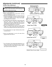
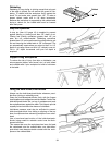
The bevel stops are set at the factory, but may have
fallen out of alignment while in transit. To check for
squareness, place the included angle gauge on the out-
feed table and check fence while locked in the 90° posi-
tion.
To ensure accuracy and repeatability of the stops,
the bottom of the outfeed side of the fence should
rest firmly against the outfeed table and against the
head of the stop screw. Make sure that the infeed table
does not interfere with the accuracy of measurement.
The infeed table should be lowered to a depth of at least
1/16". Using the stops, check the fence for accuracy. If
the fence is not square to the outfeed table, at 90°, 45°
or 135° perform the following procedure:
WARNING: To reduce the risk of injury from acci-
dental start, make sure switch is “OFF” and plug is not
connected to power source outlet.
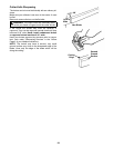
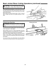
90° Bevel Stop Adjustment
1. Loosen bevel lock handle.
2. Make sure fence is tight against the stop and check the
angle using the included angle gauge.
3. Loosen the jam nut on the 90° stop screw.
4. Using the angle gauge, square the fence to the out-
feed table and tighten the bevel lock handle.
5. Turn the stop screw so it touches the stop. Tighten the
jam nut.
6. Loosen the bevel lock handle.
7. Move the fence to any angle and then return it to the
index. Check for accuracy with angle adjustment
gauge.
45° Bevel stop adjustment.
1. Loosen bevel lock handle.
2. Pivot the fence to the 45° stop and check with the
angle gauge.
3. If any adjustment is neccesary loosen the jam nut on
the 45° stop screw.
4. Set the fence to 45° using the angle gauge and lock
the bevel lock handle.
5. Turn the stop screw so it touches the stop. Tighten the
jam nut.
6. Loosen the bevel lock handle and move the fence to
any angle and back to 45°. Check for accuracy with
the angle gauge.
135° Bevel stop adjustment
1. Loosen bevel lock handle.
2. Flip the 90° stop bar out of the way and move the
fence until it contacts the 135° stop. Check with the
angle gauge.
3. If any adjustment is necessary loosen the jam nut on
the 135° stop screw.
4. Using the angle gauge, set the fence at 135° to the
outfeed table and tighten the bevel lock handle.
5. Turn the stop screw so it touches the stop. Tighten the
jam nut.
6. Loosen the bevel lock handle and move the fence to
any angle and back to 135°. Check for accuracy with
the angle gauge.
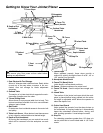
Safety Instructions for Basic Jointer/Planer Operation
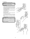
Before Each Use
Inspect your jointer/planer.
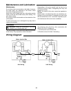
WARNING: The 2-1/2 inch jointer/planer pulley and
the 3-1/2 inch motor pulley furnished will run the cutter
head at about 5000 RPM when used with a 3450 RPM
motor. Use of different types of pulleys or motors will
change this speed and could cause jamming, binding,
kickback, thrown blades or other dangers. To prevent
serious personal injury do not change original motor or
pulleys.
• To reduce the risk of injury from accidental starting,
always turn switch off, remove switch key and unplug
jointer/planer before installing or removing any blade,
accessory or attachment or making any adjustments.
• If any part is missing, bent or broken in any way, or any
electrical part does not work properly, turn the jointer/
planer off and unplug the jointer/planer.
• Replace damaged or missing parts before using the
jointer/planer again.
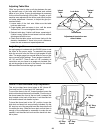
• Make sure the cutter head turns in the right direction.
The top should move toward the infeed table. Call an
Authorized Service Center for help if the cutter head
turns the wrong way.
• Keep Jointer/Planer interior, free of wood chips and
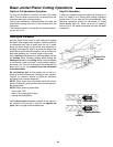
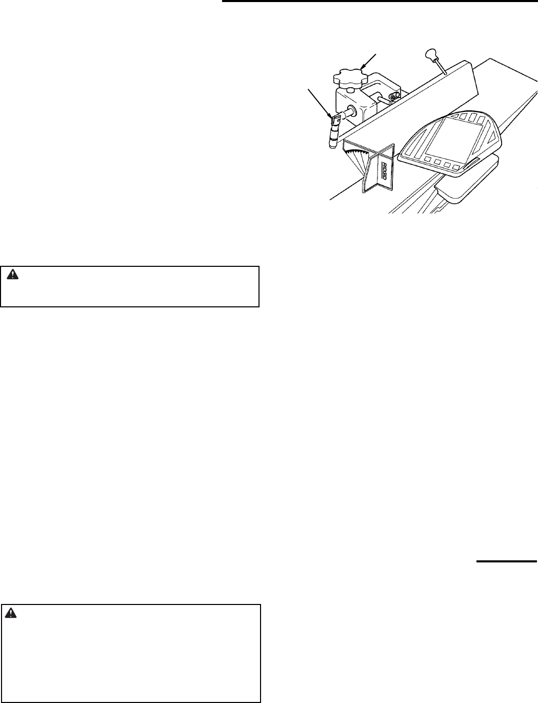
Bevel Lock
Handle
Fence Slide
Lock Knob