


14
Assembly (continued)
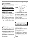
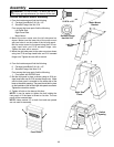
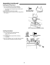
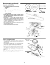
Install the Leveling Feet
1. Turn the base upside down.
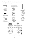
2. From the hardware pack find the following:
4 Rubber Leveling Feet
8 Flat Washer 3/8
8 Hex Nut 3/8
3. Thread one 3/8 nut onto each of the leveling feet until
the nut is 1/2" from the foot. Do this for all four feet.
4. Attach the leveling feet as shown. Place one 3/8
washer on the bottom side of the foot mount tab and
one washer on top. Bolt the feet in place with the sec-
ond 3/8 nut. Tighten the nuts down with a wrench.
NOTE: Once the jointer is in its permanent location the
leveling feet may need to be adjusted.
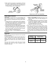
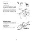
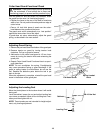
Mounting the Motor
1. Turn the cabinet upside down and place a 4 x 4 block
under the right side of the cabinet so the base is tilted
as shown. This will elevate the motor mount so it is
level with the floor making assembly easier.
2. From the hardware pack find the following:
4 Carriage Head Bolts 5/16-18 x 1/2"
4 Serrated Flange Hex Nuts 5/16
2 Machine Screws with Washer Head 3/16"
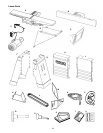
From among the loose parts find the following:
1 Motor and Switch Assembly
3. Place the motor on the motor mount as shown. Make
sure the motor shaft faces the rear of the cabinet
(away from the side with RIDGID label).
4. Bolt the motor to the motor mount using the four 5/16 car-
riage head bolts and four 5/16 serrated flange nuts. The
bolts should be placed through the motor mount into the
motor bracket as shown. Do not tighten the bolts at this
time.
5. Using the two 3/16 screws, mount the switch into place
as shown. Make sure the switch is right side up.
Leveling Foot
3/8-16 Hex Nut
Cabinet
˜
B
o
t
t
o
m
Leveling Foot
3/8 Flat Washer
Machine Screw
3/16-24 x 3/8
Carriage Head Bolt
5/16-18 x 1/2"
w/Washer Head
Serrated Flange
Hex Nut 5/16
Motor Assembl
y
with Switch