


25
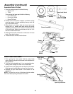
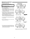
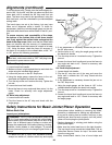
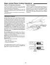
Adjusting Table Gibs
“Gibs” are provided to take up all play between the mat-
ing dovetail ways of the base and infeed and outfeed
tables of your jointer. Proper gib adjustment is necessary
for the correct functioning of the jointer. The gibs on your
machine were adjusted at the factory and should require
no further adjustment. However, to adjust the gibs pro-
ceed as follows:
1. Loosen each of the lock nuts. Make sure the table
locks are also loose.
2. Finger tighten each set screw in turn, until the screw
“bottoms out”. Do not overtighten the screws.
3. Recheck table play. If table is still loose, repeat step 2.
If table is snug, tighten the set screw lock nuts without
allowing set screws to turn.
4. Check that the table raises and lowers freely with the
elevation handwheel. If there is too much resistance,
loosen the set screws and repeat adjustment.
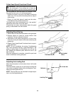
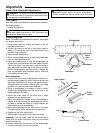
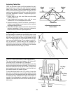
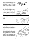
Angle Gauge Use
An angle gauge is included with the RIDGID jointer to set
the fence at the proper angle. To assemble the gauge
slide the one side over the other at right angles to each
other. The angle gauge has several faces for some of the
more common angle settings. These angles include 90°,
45°, 30° and 22.5°. There is also a 0°-45° protractor on
one side to set your fence to an angle not provided. Sim-
ply set the gauge at the end of the fence on the outfeed
table as shown and set the angle you need.
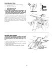
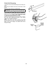
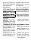
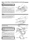
Fence Tilt Use and Bevel Stop Adjustment
This tool provides fence bevel stops at 90° (fence 90°
from bed) and 45° forward and 135° backward.
To move the fence to the 45° forward position loosen the
slide lock knob and the bevel lock handle. Pivot the top of
the fence toward the front of the tool until it contacts the
stop located on the back of the fence. Lock the slide lock
knob and the bevel lock handle in place.
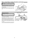
To bevel the fence back to the 135° position, loosen the
slide lock and bevel lock as previously indicated, flip the
90° stop bar out of the way and bevel the fence back until
it contacts the stop. Slide the fence back so that there is
enough of the cutterhead is accessible to make the cut
needed. Lock the slide lock knob and the bevel lock han-
dle in place.
Lock Nuts
Table Locks
Adjustments located on rear
side of tables
Infeed
Table
Outfeed
Table
45° Stop
Screw
90° Stop
Screw
135° Stop
Screw
90° Stop
Bar