


8
Motor Specifications and Electrical Requirements (continued)
General Electrical Connections
DANGER: To reduce the risk of electrocution:
1. Use only identical replacement parts when servic-
ing. Servicing should be performed by a qualified
service technician.
2. Do not use in rain or where floor is wet.
This tool is intended for indoor residential use only.
WARNING: Do not permit fingers to touch the ter-
minals of plug when installing or removing the plug to
or from the outlet.
If power cord is worn or cut, or damaged in any way,
have it replaced immediately.
110-120 Volt, 60 Hz. Tool Information
The plug supplied on your tool may not fit into the outlet
you are planning to use. Your local electrical code may
require slightly different power cord plug connections. If
these differences exist refer to and make the proper
adjustments per your local code before your tool is
plugged in and turned on.
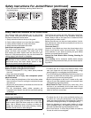
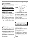
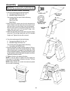
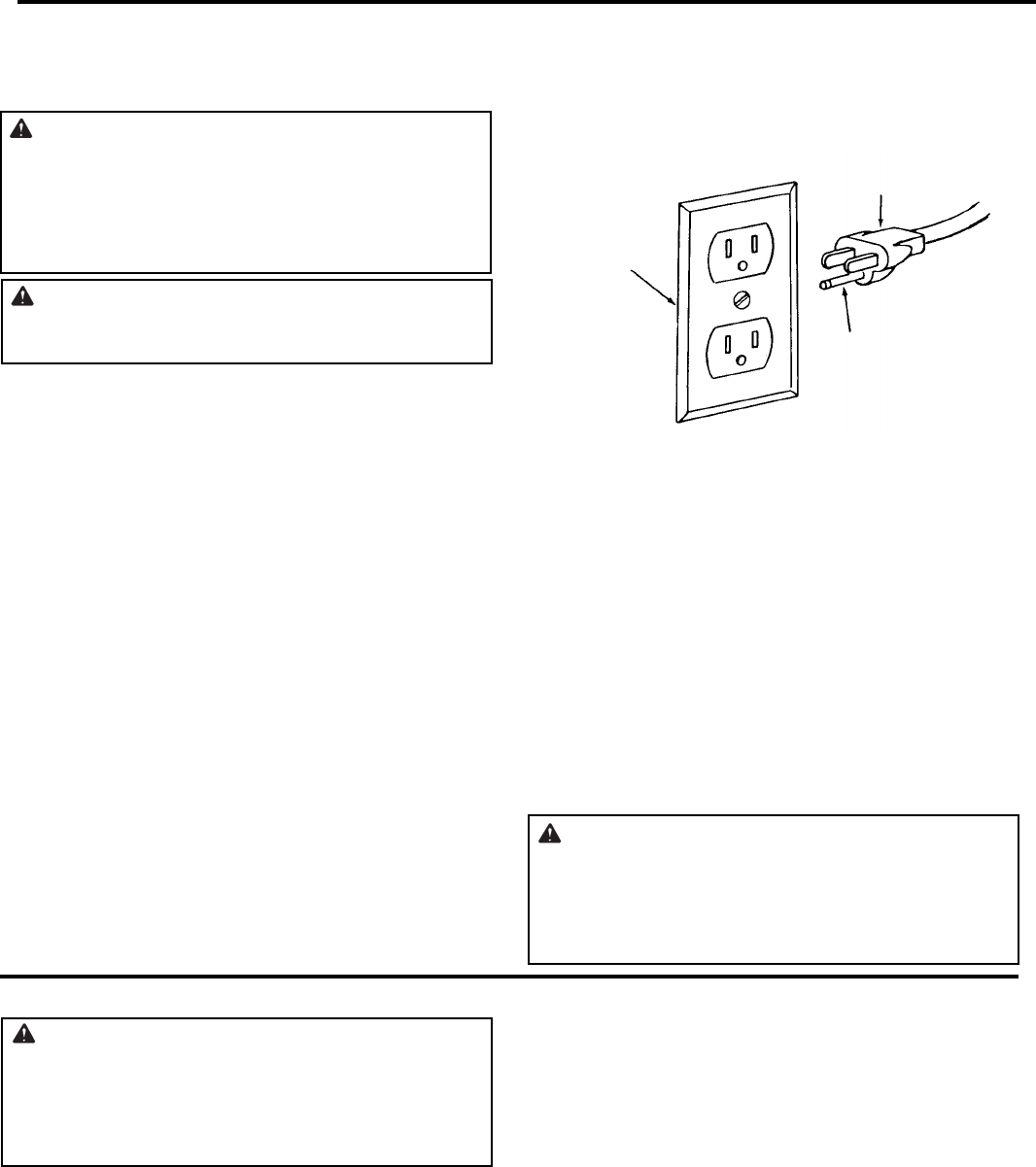
In the event of a malfunction or breakdown, grounding
provides a path of least resistance for electric current to
reduce the risk of electric shock. This tool is equipped
with an electric cord having an equipment grounding con-
ductor and a grounding plug, as shown. The plug must
be plugged into a matching outlet that is properly
installed and grounded in accordance with all local codes
and ordinances.
Do not modify the plug provided. If it will not fit the outlet,
have the proper outlet installed by a qualified electrician.
Improper connection of the equipment grounding con-
ductor can result in a risk of electric shock. The conduc-
tor with insulation having an outer surface that is green
with or without yellow stripes is the equipment grounding
conductor. If repair or replacement of the electric cord or
plug is necessary, do not connect the equipment-ground-
ing conductor to a live terminal.
If the grounding instructions are not completely under-
stood, or if you are in doubt as to whether the tool is prop-
erly grounded check with a qualified electrician or service
personnel.
WARNING: If not properly grounded, this tool can
cause an electrical shock, particularly when used in
damp locations, in proximity to plumbing, or out of
doors. If an electrical shock occurs there is the poten-
tial of a secondary hazard, such as your hands con-
tacting the knives.
Changing Motor Voltage
WARNING: If not properly grounded, this tool can
cause an electrical shock, particularly when used in
damp locations, in proximity to plumbing, or out of
doors. If an electrical shock occurs there is the poten-
tial of a secondary hazard, such as your hands con-
tacting the knives.
NOTE: The jointer is prewired at the factory for 120V
operation. Use the following procedure to change motor
voltage. To change to 240V application an additional wire
nut is supplied from the factory. This part is included in
the loose parts.
1. Unplug the jointer/planer before making or changing
any connections. Open the motor junction box cover
located on the side of the motor.
2. Remove and discard the electrical tape from the wire
nuts. Remove wire nuts.
3. Reconnect the leads as shown in the “Wiring Diagram”
section at the rear of manual.
4. Reinstall the wire nuts and wrap with two layers of new
U.L. listed electrical tape per wire nut.
5. Recheck your wiring to the wiring diagrams. Do this so
you can be sure that the wiring is correct.
6. Reinstall the junction box cover.
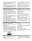
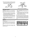
7. Cut off the 120 volt power cord plug and replace it with
a (3 blade) 240 volt 15 amp U.L. listed plug. (See illus-
tration of 240V plug & receptacle.) Connect the power
cord white and black leads, respectively, to the “hot”
plug blade terminals and connect the power cord
green grounding wire to the plug ground prong termi-
nal.
8. Plug your jointer into a 220-240V, 15 amp, 3 blade
receptacle.
Properly
Grounded
Outlet
3-Prong Plug
Grounding
Prong