


12
Assembly (continued)
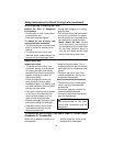
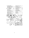
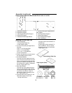
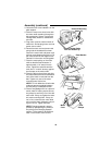
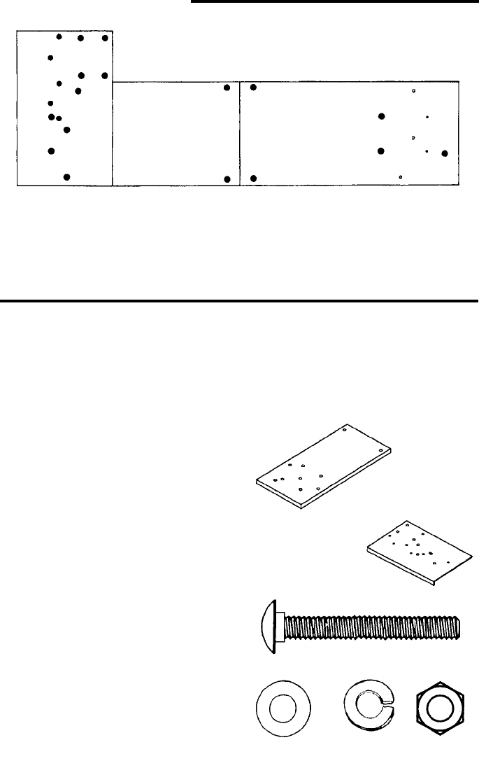
Holes Used for Mounting Boards and Wood Lathe to Leg Set
A - Board/Side Support
B - Board/Side Support
C - Plate Support/Board/End Support
D - Board/End Support
E - Headstock/Plate Support/Board
F - Bracket Plate/Plate Support/Board/
Side Support
G - Belt Guard/Plate Support
H - Motor/Plate Support
J - Cord Clamps/Plate Support
K - Rear Foot/Board
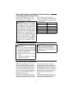
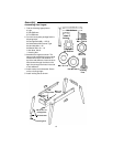
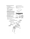
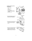
Mounting Left Side Table Top
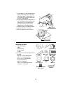
1. Find the following:
1 Particle Board Table Top
1 Plate Support (Steel)
2. From the loose parts package find the
following:
4 M6 x 1.0-45 Carriage Bolts
4 M6 x 1.0 Hex Head Nuts
4 6.5 x 19 x 1.6 Flat Washers
4 6mm Lockwashers
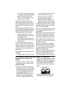
3. Position the table top on the left side of
the assembled legset as shown
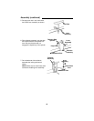
4. Front Side Stiffeners
Face the front of the legset and count
over from the left one slot and one hole.
Place a carriage bolt through the table
top (hole A) and the side stiffener. Fas-
ten in place with a washer, lockwasher
and nut. Finger tighten only.
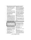
5. Rear Side Stiffener
Face the rear of the legset and count
over from the right two holes. Place a
carriage bolt through the table top (hole
A) and the side stiffener. Fasten in
place with a washer, lockwasher and
nut. Finger tighten only.
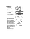
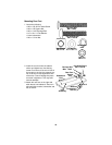
6. Locate the two holes marked C in the
steel plate support. Place bolts;
- through these holes
- through the two holes marked C on
the table top
- and through the holes marked C in
the End Stiffener. Place a washer,
lockwasher and nut on these bolts.
Finger tighten only.
A
B
C
D
E
G
F
HH
H
A
C
H
B
D
E
G
J
J
K
G
Plate Support (Steel)
Carriage Bolt
M6 x 1.0-45
Flat Washer Nut Hex
6
.5 x 19 x 1.6 M6 x 1.0
Lockwasher
6mm
Particle Board Table To
p