


17
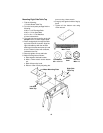
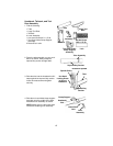
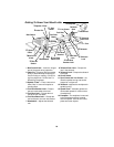
Headstock, Tailstock, and Tool
Rest Assembly
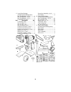
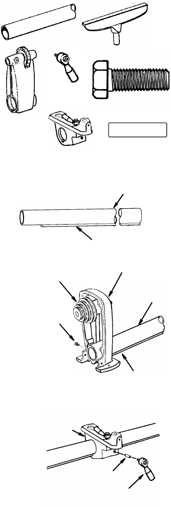
1. Find the following:
1Tube
1 Large Tool Rest
1Tailstock
2Lever Assembly
1 Hex Head Screw M10 x 1.5-30
1 Tool Rest Holder/Clamp Support
Assembly
2 Brass Shoe Locks
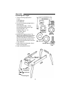
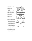
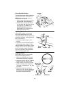
2. Place the tube assembly on your work-
bench as shown. Always keep the
squared key section straight down.
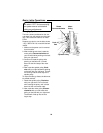
3. Slide the tube into the headstock until it
stops against the squared key section.
Insert hex head screw and tighten
securely.
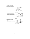
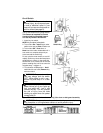
4. Slide the tool rest holder/clamp support
assembly onto the middle of the tube.
Assemble lever assembly as shown.
NOTE: Make sure to insert brass shoe
lock before installing lever assembly.
Tube
Lever
Brass Shoe
Hex Hd Screw
M10 x 1.5-30
Large Too
l
Rest
Tailstock
Tool Rest Holder
Clamp Support
Assembly
Lock
Assembly
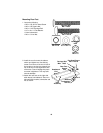
Tube Assembly
Squared Key Section
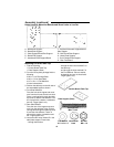
Spindle Pulley
Headstock Spindle
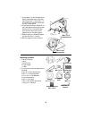
Tube
Squared Key
Section
Hex Head
in Rear of
Headstock
Locking Screw
H
eadstock
End
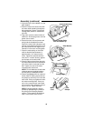
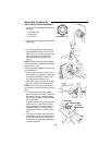
Clamp Support
Brass Shoe
Lever
Lock
Assembly