18
Assembly (continued)
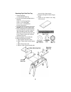
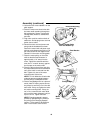
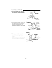
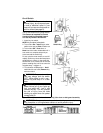
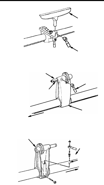
5. Set large tool rest in tool rest holder
and install lever assembly as shown.
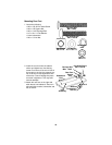
6. Slide tailstock assembly onto the tube
and install tailstock ram spindle lock
lever. Be sure that the stud nut
engages the keyed way of the spindle.
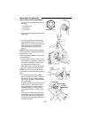
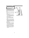
7. On the backside of the tailstock,
assemble the locking devices as
shown.
NOTE: Make sure to insert brass shoe
lock before installing lever assembly.
Tool Rest
Lever
Assemb
ly
Lever
Tailstock Ram
Keyed Way
Headstock End
Tailstock
Spindle
Assemb
ly
Assembly
Lever
Headstock End
Tailstock
Brass Sho
e
Lock
Assembly
Assembly


