


14
Assembly (continued)
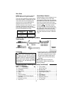
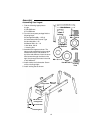
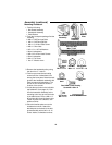
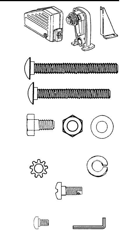
Mounting Headstock
1. Find the following:
1 Belt Guard Assembly
1 Headstock Assembly
1 Plate Bracket
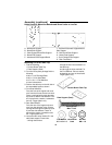
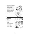
2. From the loose parts package find the
following:
2 M6 x 1.0-65 Carriage Bolts
1 M6 x 1.0-45 Carriage Bolt
1 M6 x 1.0-12 Hex Head Screw
4 M6 x 1.0 Hex Nuts
4 6.5 x 19 x 1.6 Flat Washers
4 6mm Lockwashers
4 M5 x 0.8-12 Pan Head Screws
4 5mm Lockwasher
3 M4 x 0.7-6 Screw
1 Hex “L” Wrench 4mm
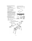
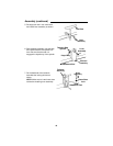
3. Remove the headstock pulley using
the 4mm hex “L” wrench.
4. Find four pan head thread cutting
screws and four lockwashers from
among the loose parts. Attach the belt
guard to the headstock assembly with
these screws and lockwashers. The
arrows in this illustration show the
location of the screws.
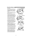
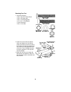
5. Locate the two holes on the left table
top Labeled E (from page 12). Posi-
tion the headstock assembly so the
mounting holes line-up with the holes
in the table board. Place a M6 x 1.0-
65 carriage bolt, through these holes.
Fasten in place with a washer, lock-
washer and nut.
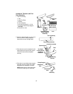
6. Place the bracket plate next to the
headstock as shown. Attach the
bracket plate to the back of the belt
guard assembly with a M6 x 1.0-12
screw, washer, lockwasher and nut.
Belt Guard
Assembly
Bracke
t
Pan Screw
M4 x 0.7-6
Hex Head
M6 x 1.0-12
Hex “L” Wrench 4mm
Flat Washe
r
Nut Hex
6.5 x 19 x 1.
6
M6 x 1.0
Lockwasher
6mm
Plate
Headstock
Assembly
Screw
Carriage Bolt
M6 x 1.0-45
Carriage Bolt
M6 x 1.0-65
Pan Head Thread Cutting
Screw M5 x 0.8 x 12
Lockwasher
5mm