


20
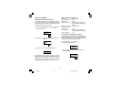
OPERATING MODE
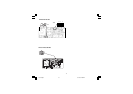
1) Remove the instrument from its case.
2) Set switch V101 to the closed position.
3) Re-insert the instrument in its case.
4) Switch on the instrument.
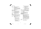
Normal Display Mode
On powerup the device starts in the "Normal Display
Mode."
By pressing the or key, it is possible to change the
displayed information; therefore, one of the following
display modes can be selected:
1) The upper display shows the measured value while
the lower display shows the "Pu" (Process variable)
2) The upper display shows the setpoint threshold while
the lower display shows "Su." If this display was active
at power down, it will be active at powerup.
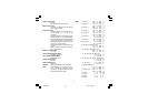
3) The upper display shows the setpoint1 threshold
while the lower display shows "S1." This information
is available only if C1 = Hi.Lo If this display was active
at power down, it will be active at powerup
4) The upper display shows the total time (hh.mm) of the
last reset condition while the lower displays shows “t.”
(if no data is available, the upper display will show
"- - - -" ). The information is lost at power down and at
powerup the device will display the process variable.
5) The upper display shows the maximum value of
process variable detected during the last "reset" con-
dition while the lower display shows "Ph." (if no data
is available, the upper display will show “- - - -” ). This
information is not available if C1 = Lo. The information
is lost at power down and at powerup the device will
display the process variable.
NOTE: In case the reset condition was generated by a
fault condition in the measure variable, the upper display
will indicate
"m.Err"
6) The upper display shows the minimum value of the
process variable detected during the last "reset" con-
dition while the lower display shows "PL.” (if no data
is available, the upper display will show “- - - -”) This
information is not available if C1 = Hi. The information
is lost at power down and at powerup the device will
display the process variable .
NOTE: in case the “reset condition” was generated by
a fault condition in the measure variable, the upper
display will indicate
"m.Err"
At powerup the display will show the process variable
unless otherwise stated in one of the above display
options
If, at power off, the device was in reset condition and
configured to save it (C4 = 0), and/or it was programmed
for manual reset at startup (C3 = 1), then at the next
power up the lower display will be flashing.
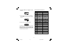
Indicators
“RESET“ = Indicates control output status
as follows:
a) With configuration parameter
C2 = 0
LED ON when Output is OFF
LED OFF when Output is ON
b) With configuration parameter
C2 = 1
LED flashes when Output is OFF
LED ON when Output is OFF
and acknowledged
LED OFF when Output is ON
“ALM” = Indicates alarm status as follows:
Flashes when alarm is ON
ON when alarm has been
acknowledged
OFF when alarm is OFF
7sl-3-00.p65 9/17/02, 2:41 PM20