


7
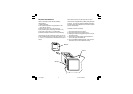
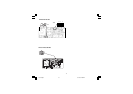
WIRING GUIDELINES
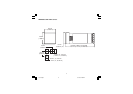
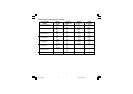
Terminal Layout
1
3
4
5
6
7
8
9
10
2
11
13
14
15
12
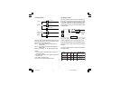
RS485
NC
OUT 2
C
LINEAR
NO
C
PWR LINE
100/240Vac
24 Vac/dc
A/A'
B/B'
NO
DIG 1
OUT 1
C
+
_
TC
RTD
+
_
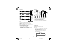
daoL
tnerruC
C
(µ )F
R
(Ω)
P
)W(
dnarotsiseR
egatloVroticapaC
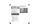
Am04<740.00012/1caV062
Am051<1.0222 062caV
pmA5.0<33.0742 062caV
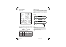
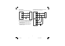
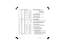
A) Measuring Inputs
10
9
+
Shield
_
9
Shield
+
10
_
NOTE:
1) Do not run input wires with power cables.
2) For TC wiring use proper compensating cable,
preferably shielded (see Thermocouple Compen-
sating Cable Color Codes).
3) Shielded cable should be grounded at one end
only.
NOTE: Any external components (like Zener diodes,
etc.) connected between sensor and input terminals may
cause errors in measurement due to excessive and/or
not balanced line resistance or possible leakage cur-
rents.
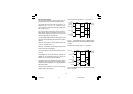
TC Input
RC
NOTE: When a relay output is used to drive an inductive
load, connect an external snubber network (RC) across
the terminals:
in accordance with the following table:
7sl-1-00.p65 9/17/02, 2:39 PM7